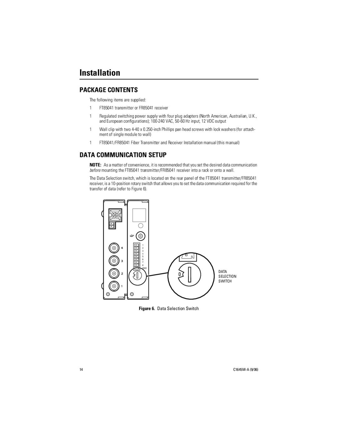
FR85041 specifications
The Pelco FR85041 is a cutting-edge indoor network camera that combines high-performance features with advanced technologies to provide exceptional surveillance capabilities. Designed for a wide range of applications, including commercial, retail, and institutional environments, the FR85041 camera offers a robust solution for those seeking to enhance their security systems.One of the standout features of the FR85041 is its high-definition imaging capability. The camera delivers 1080p resolution at 30 frames per second, ensuring clear and detailed video footage. This high resolution is essential for identifying faces, license plates, and other critical details that can be pivotal in security investigations.
In addition to its impressive resolution, the FR85041 incorporates advanced low-light performance through its Wide Dynamic Range (WDR) technology. This feature allows the camera to produce clear images in challenging lighting conditions, such as stark contrasts between bright and dark areas. This capability is particularly beneficial for monitoring entrance points and areas with mixed lighting.
The FR85041 also employs H.264 video compression, which helps to optimize bandwidth utilization without sacrificing video quality. This technology is crucial for efficient storage management and enables users to retain more footage without overwhelming their network resources. Moreover, it can easily integrate with existing IP surveillance systems, making it a flexible choice for users looking to upgrade their current setups.
Another notable characteristic of the Pelco FR85041 is its built-in analytics. The camera features intelligent video analysis capabilities that can detect motion, trespassing, and loitering, thus improving the efficiency of monitoring efforts. Users can set up custom alerts to notify them of any suspicious activity, enabling a quicker response to potential threats.
The FR85041 also boasts a durable design that meets various environmental standards, making it suitable for use in a variety of indoor settings. Its discrete and unobtrusive form factor allows it to blend seamlessly into different environments without drawing attention.
In conclusion, the Pelco FR85041 is a powerful indoor network camera that combines high-resolution imaging, advanced low-light performance, video compression, and intelligent analytics. Its robust design and flexible integration options make it a leading choice for users seeking reliable surveillance solutions in various professional settings.

