Camera Layout
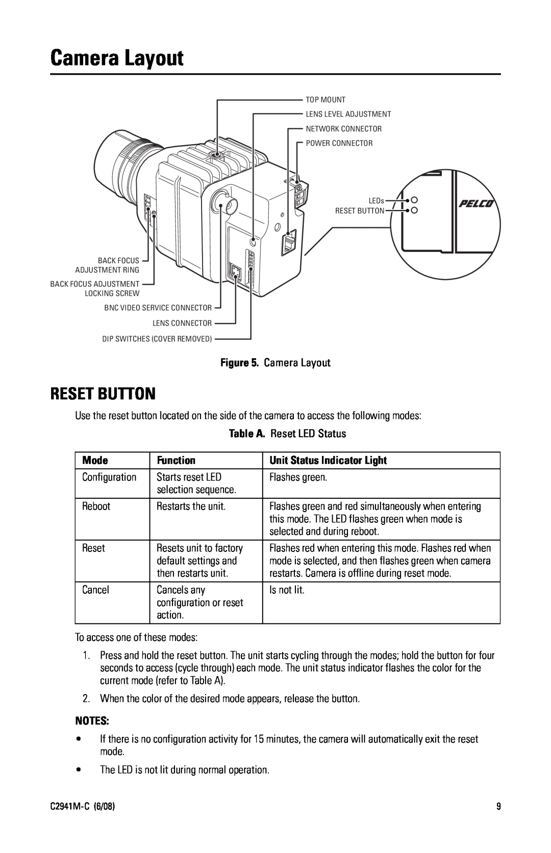
TOP MOUNT
![]() LENS LEVEL ADJUSTMENT
LENS LEVEL ADJUSTMENT
![]() NETWORK CONNECTOR
NETWORK CONNECTOR
![]() POWER CONNECTOR
POWER CONNECTOR
LEDs ![]()
![]()
RESET BUTTON ![]()
![]()
BACK FOCUS ![]()
ADJUSTMENT RING
BACK FOCUS ADJUSTMENT ![]()
LOCKING SCREW
BNC VIDEO SERVICE CONNECTOR ![]()
LENS CONNECTOR ![]()
DIP SWITCHES (COVER REMOVED) ![]()
Figure 5. Camera Layout
RESET BUTTON
Use the reset button located on the side of the camera to access the following modes: Table A. Reset LED Status
Mode | Function | Unit Status Indicator Light |
|
|
|
Configuration | Starts reset LED | Flashes green. |
| selection sequence. |
|
Reboot | Restarts the unit. | Flashes green and red simultaneously when entering |
|
| this mode. The LED flashes green when mode is |
|
| selected and during reboot. |
Reset | Resets unit to factory | Flashes red when entering this mode. Flashes red when |
| default settings and | mode is selected, and then flashes green when camera |
| then restarts unit. | restarts. Camera is offline during reset mode. |
Cancel | Cancels any | Is not lit. |
| configuration or reset |
|
| action. |
|
To access one of these modes:
1.Press and hold the reset button. The unit starts cycling through the modes; hold the button for four seconds to access (cycle through) each mode. The unit status indicator flashes the color for the current mode (refer to Table A).
2.When the color of the desired mode appears, release the button.
NOTES:
•If there is no configuration activity for 15 minutes, the camera will automatically exit the reset mode.
•The LED is not lit during normal operation.
9 |