Manuals
/
Pelco
/
Household Appliance
/
Home Security System
Pelco
Not ICS110-CW
manual
4S ELECTRICAL BOX INSTALLATION
Models:
Not ICS110-CW
1
9
28
28
Download
28 pages
7.51 Kb
6
7
8
9
10
11
12
13
Install
Warranty
Back Box Connectors
Camera Adjustments
Service Connector
Switch Settings
Page 9
Image 9
Page 8
Page 10
Page 9
Image 9
Page 8
Page 10
Contents
Integrated Camera System Wide Dynamic Range WDR
C3406M-D 1/07
ICS110-CW Series Camclosure
I N S T A L L A T I O N
Page
Side Conduit Installation
Contents
Varifocal Lens Zoom and Focus Adjustments
Vertical Phase Adjustment 24 VAC Operation Only
List of Illustrations
RADIO AND TELEVISION INTERFERENCE
Regulatory Notices
MODELS
Description
Figure 1. Package Components
SHOWN ACTUAL SIZE
Cover and Back Box Installation
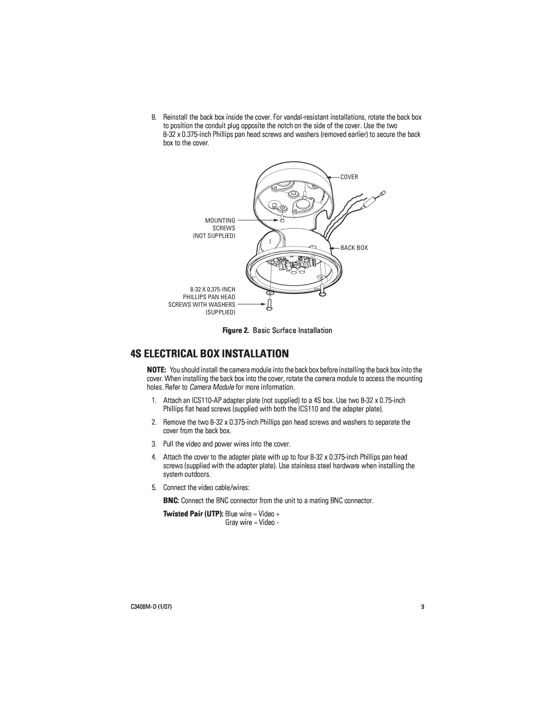
BASIC SURFACE INSTALLATION
UNSHIELDED TWISTED PAIR UTP VIDEO
4S ELECTRICAL BOX INSTALLATION
ADAPTER PLATE
404 PLASTER RING INSTALLATION
SIDE CONDUIT INSTALLATION
8-32 X 0.375-INCH PHILLIPS PAN HEAD SCREWS WITH WASHERS SUPPLIED
COVER 0.75-INCH CONDUIT CONNECTOR BACK BOX REMOVE CONDUIT PLUG
MODULE REMOVAL
Camera Module
HEATER BOARD CONNECTOR SERVICECAMERA CONNECTORCONNECTOR
Figure 7. Back Box Connectors
CAMERA ORIENTATION
MODULE INSTALLATION
VARIFOCAL LENS ZOOM AND FOCUS ADJUSTMENTS
Camera Adjustments
SWITCH SETTINGS
ADJUSTING THE VERTICAL PHASE
VERTICAL PHASE ADJUSTMENT 24 VAC OPERATION ONLY
Tilt
Camera Positioning
Figure 12. Positioning the Camera
Rotation
Install Dome and Trim Ring
Service Connector
1 2.5 mm monaural headphone plug 1 CPM 88 miniature coaxial connector
Specifications
CAMERA
LENS
Electrical
BACKBOX
General
Design and product specifications subject to change without notice
C3406M-D 1/07
WARRANTY
PRODUCT WARRANTY AND RETURN INFORMATION
REVISION HISTORY
RETURNS
USA & Canada Tel 800/289-9100 Fax 800/289-9150 International
Worldwide Headquarters 3500 Pelco Way Clovis, California 93612 USA
Tel 1-559/292-1981 Fax 1-559/348-1120
ISO9001
Top
Page
Image
Contents