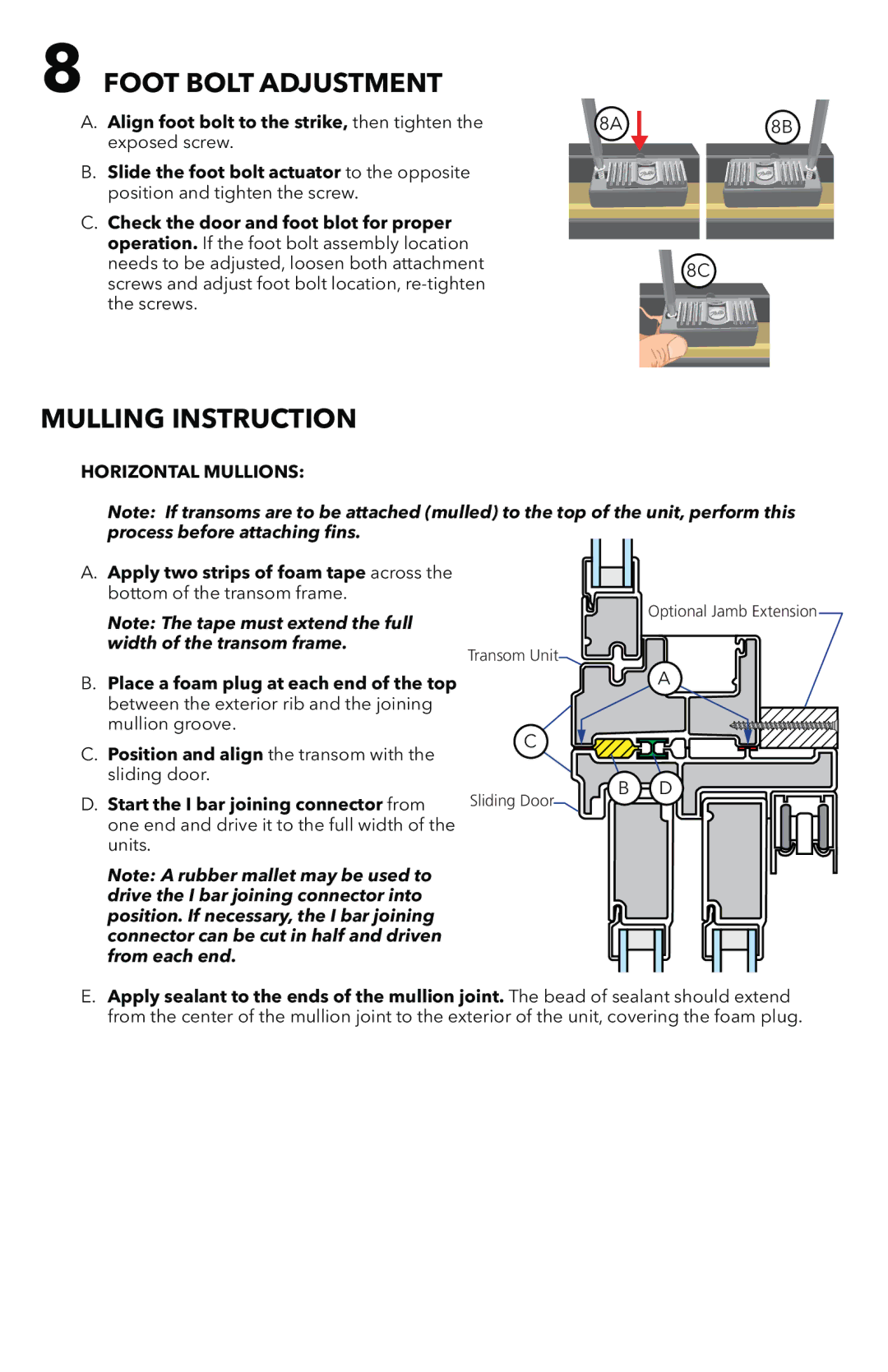
803V0102 specifications
The Pella 803V0102 is an advanced window solution that combines modern design with cutting-edge technology, making it an ideal choice for homeowners seeking both aesthetics and performance. Known for its energy efficiency, the Pella 803V0102 features triple-pane glass that significantly reduces heat transfer, ensuring that homes remain comfortable regardless of the season. This multi-layered glass structure helps to keep indoor heating and cooling efforts efficient, thereby reducing energy bills over time.One of the standout characteristics of the Pella 803V0102 is its innovative Low-E glass coating. This specialized coating reflects infrared light while allowing visible light to pass through, maximizing natural light while minimizing heat loss. The innovative design also contributes to the window's ability to reduce harmful UV rays, protecting furniture and flooring from fading, which is often a concern in sun-drenched areas.
In terms of durability, the Pella 803V0102 is engineered with robust frames crafted from high-quality materials. The frame construction is designed to withstand weather extremes, ensuring longevity and stability. Additionally, the window is equipped with a water-repellent exterior finish, which protects against moisture damage while requiring minimal maintenance over the years.
The Pella 803V0102 also boasts noise-reduction technologies, making it an excellent choice for homes in busy urban environments. The combination of multiple glass panes and specialized seals effectively dampens outside noises, creating a tranquil indoor atmosphere.
Security is another priority for the Pella 803V0102. The window is fitted with advanced locking mechanisms, which offer enhanced protection against break-ins, providing peace of mind for homeowners. Furthermore, the design of the window can accommodate various styles, making it suitable for different architectural preferences from traditional to contemporary homes.
Easy installation and customization options further enhance the appeal of the Pella 803V0102. Homeowners can choose from a variety of finishes, colors, and grille patterns to match their home’s style seamlessly.
In summary, the Pella 803V0102 represents a perfect blend of innovation, efficiency, and style. Its energy-saving features, acoustic performance, durability, and security technologies make it a leading choice for those looking to invest in high-quality windows that enhance both comfort and safety in their homes. Whether upgrading an existing home or building a new one, the Pella 803V0102 is poised to deliver exceptional value and performance.

