3
Connecting the ScreenLogic Video & Lighting Protocol Adapter
The following describes how to connect the Video & Lighting Protocol adapter to an existing ScreenLogic system.
1.Connect the provided RJ45 (CAT5) cable to an available port (1, 2, 3, or 4) on the ScreenLogic wireless router. Connect the other end of the cable to the LAN port on the Video & Lighting Protocol adapter (see diagram on page 2).
2.Lights cable connection: Connect an RJ45 (CAT5) cable to the COM 1 port on the adapter. Connect the other end of the cable to the DB9M/RJ45 adapter. Connect the DB9M/RJ45 adapter to the
3.Camera cable connection: Connect AC power plug to the video camera(s). Connect the RJ45 camera cable to port 1, 2, 3, or 4 on the ScreenLogic wireless router (see diagram on page 2).
If additional cameras are being installed, a Network Switch can be used to provide available ports. ScreenLogic supports a maximum of four cameras (see diagram on page 2).
ScreenLogic Video & Lighting Protocol Adapter Name
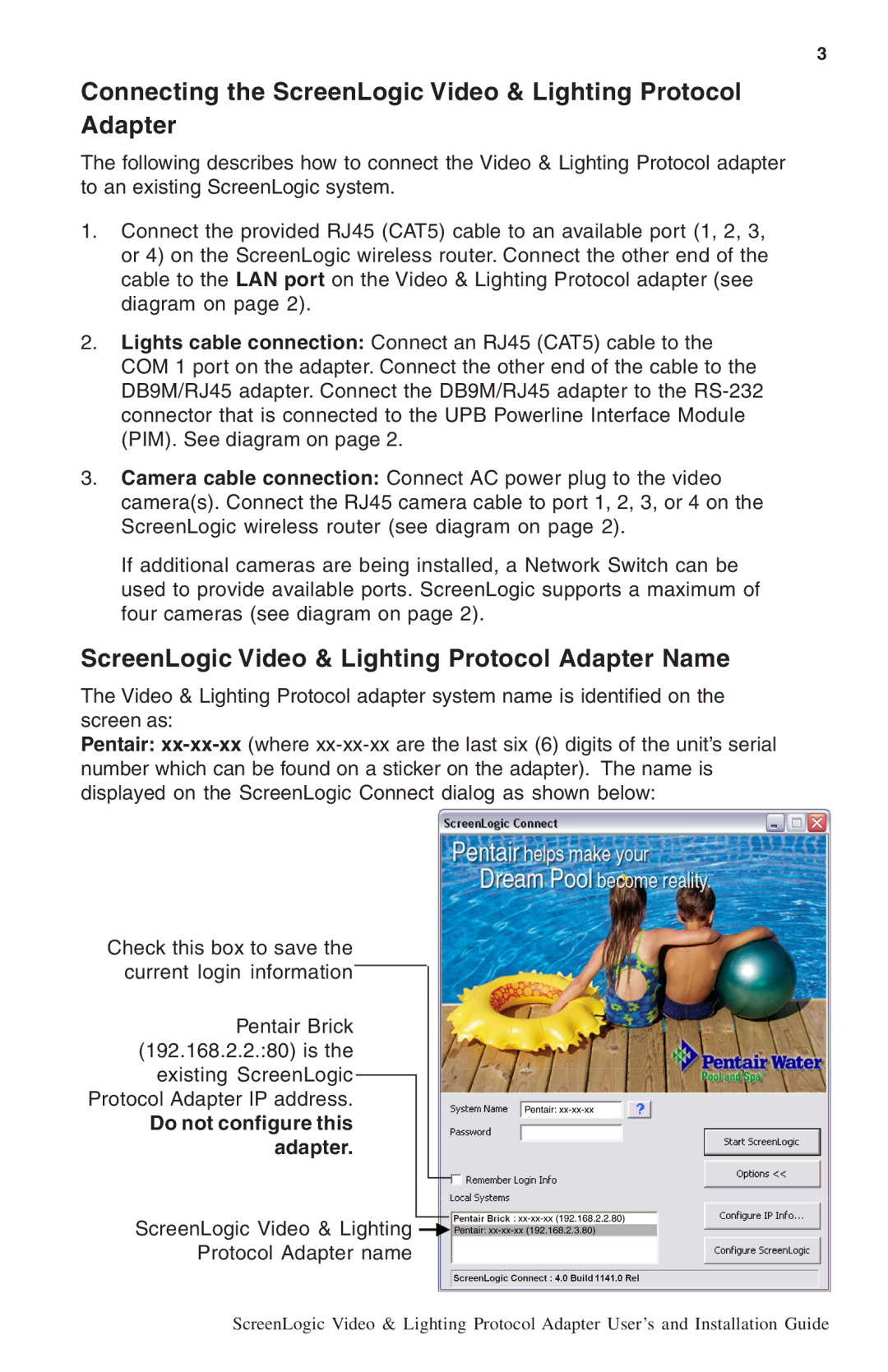
The Video & Lighting Protocol adapter system name is identified on the screen as:
Pentair:
Check this box to save the current login information
Pentair Brick (192.168.2.2.:80) is the existing ScreenLogic Protocol Adapter IP address.
Do not configure this adapter.
ScreenLogic Video & Lighting ![]()
Protocol Adapter name
ScreenLogic Video & Lighting Protocol Adapter User’s and Installation Guide