Section IV. Operation | 22 |
|
|
SAFETY CONTROLS
VACUUM AIR PRESSURE (FAN) SWITCH
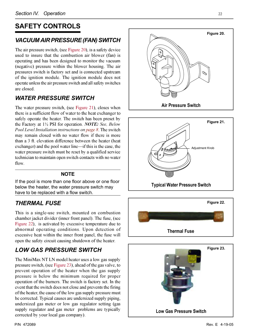
The air pressure switch, (see Figure 20), is a safety device used to insure that the combustion air blower (fan) is operating and has been designed to monitor the vacuum (negative) pressure within the blower housing. The air pressures switch is factory set and is connected upstream of the ignition module. The ignition module does not operate unless the air pressure switch and all safety switches are closed.
WATER PRESSURE SWITCH
The water pressure switch, (see Figure 21), closes when there is a sufficient flow of water to the heat exchanger to safely operate the heater. The switch has been preset by the Factory at 1½ PSI for operation. NOTE: See, Below Pool Level Installation instructions on page 8. The switch may remain closed with no water flow if there is more than a 3 ft. elevation difference between the heater (heat exchanger) and the pool water
NOTE
If the pool is more than one floor above or one floor below the heater, the water pressure switch may have to be replaced with a flow switch.
THERMAL FUSE
This is a
LOW GAS PRESSURE SWITCH
The MiniMax NT LN model heater uses a low gas supply pressure switch, (see Figure 23), ahead of the gas valve, to prevent operation of the heater when the gas supply pressure is below the minimum required for proper operation of the burners. The switch is factory set. In the event that the switch does not close and prevents the firing of the heater, the cause of the low gas supply pressure must be corrected. Typical causes are undersized supply piping, undersized gas meter or low gas regulator setting (gas supply regulator and gas meter problems are typically corrected by your local gas company).
Figure 20.
AIR PRESSURE SWITCH
Air Pressure Switch
Figure 21.
Adjustment Knob
Typical Water Pressure Switch
Figure 22.
Thermal Fuse
Figure 23.
Low Gas Pressure Switch
P/N 472089 | Rev. E |