Manuals
/
Perle Systems
/
TV and Video
/
TV Converter Box
Perle Systems
5500316-13
manual
Front and Rear Panel Components
Models:
5500316-13
1
5
23
23
Download
23 pages
40.69 Kb
1
2
3
4
5
6
7
8
Troubleshooting
Install
ALM Alarm
Connecting To The LAN
Dimension
Page 5
Image 5
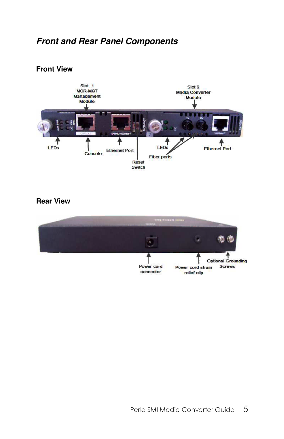
Front and Rear Panel Components
Front View
Rear View
P
ERLE
SMI M
EDIA
C
ONVERTER
G
UIDE
5
Page 4
Page 6
Page 5
Image 5
Page 4
Page 6
Contents
Perle SMI Media Converter Installation Guide
Overview
Introduction
SPF
Unpacking your SMI Media Converter
Getting to know your SMI Media Converter
Front and Rear Panel Components
Adding or Removing Modules
Installation
Powering up the SMI Media Converter
Perle SMI Media Converter Guide
Attaching the Grounding Lug
Attaching the Power Cord Strain Relief Clip
Grounding the SMI Chassis Optional
Perle SMI Media Converter Guide
Connecting To The LAN
Features
MCR-MGT Management Module
Making Connections to Management Module
MCR-MGT
Connecting To The Console Port
Perle SetIP Utility
Configuring the Management-MGT Module
Serial Console Port
Perle SMI Media Converter Guide
LED Status for the Management Module
ALM Alarm
PWR Power
100/1000
LKC Copper -Link/Activity
Loopback Mode
Troubleshooting
General
No connectivity
MCR-MGT PWR LED is RED
Cannot connect to MCR-MGT Module using an IP address
MCR-MGT PWR LED is Blinking Green
Cannot connect serially to MCR-MGT Module
Perle SMI Media Converter Guide
Dimensions
Technical Specifications for the SMI Media Converter
Ethernet Copper Cabling
FCC
Compliance Information
Details can be found at
Top
Page
Image
Contents