3 Your TV
Congratulations on your purchase, and welcome to Philips! To fully benefit from the support that Philips offers, register your product at www.philips.com/welcome.
TV overview
This section gives you an overview of commonly used TV controls and functions.
Side controls and indicators
VOLUME ![]() 5
5
4
MENU
CHANNEL ![]() 3
3
2
POWER
1
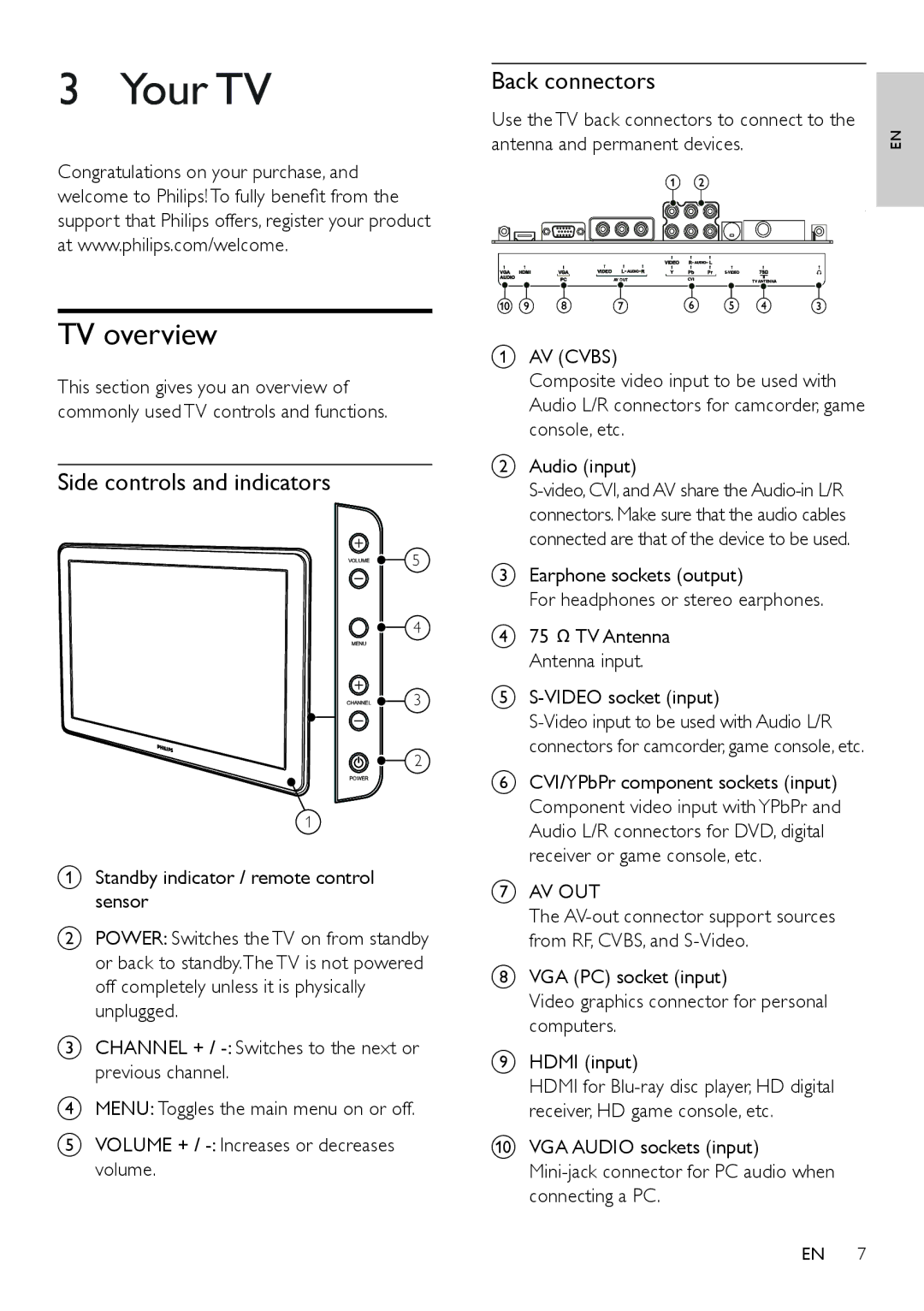
aStandby indicator / remote control sensor
bPOWER: Switches the TV on from standby or back to standby.The TV is not powered off completely unless it is physically unplugged.
cCHANNEL + /
dMENU: Toggles the main menu on or off.
eVOLUME + /
Back connectors
Use the TV back connectors to connect to the
antenna and permanent devices. | EN | |
| a b |
|
|
| |
AV OUT | CVI | TVANTENNA |
j i h g | f e | d c |
aAV (CVBS)
Composite video input to be used with Audio L/R connectors for camcorder, game console, etc.
bAudio (input)
cEarphone sockets (output)
For headphones or stereo earphones.
d75 ![]() TV Antenna Antenna input.
TV Antenna Antenna input.
e
fCVI/YPbPr component sockets (input) Component video input with YPbPr and Audio L/R connectors for DVD, digital receiver or game console, etc.
gAV OUT
The
hVGA (PC) socket (input)
Video graphics connector for personal computers.
iHDMI (input)
HDMI for
jVGA AUDIO sockets (input)
EN 7
