CONNECTING PERIPHERAL EQUIPMENT
1
2
3
Video Recorder : Playback
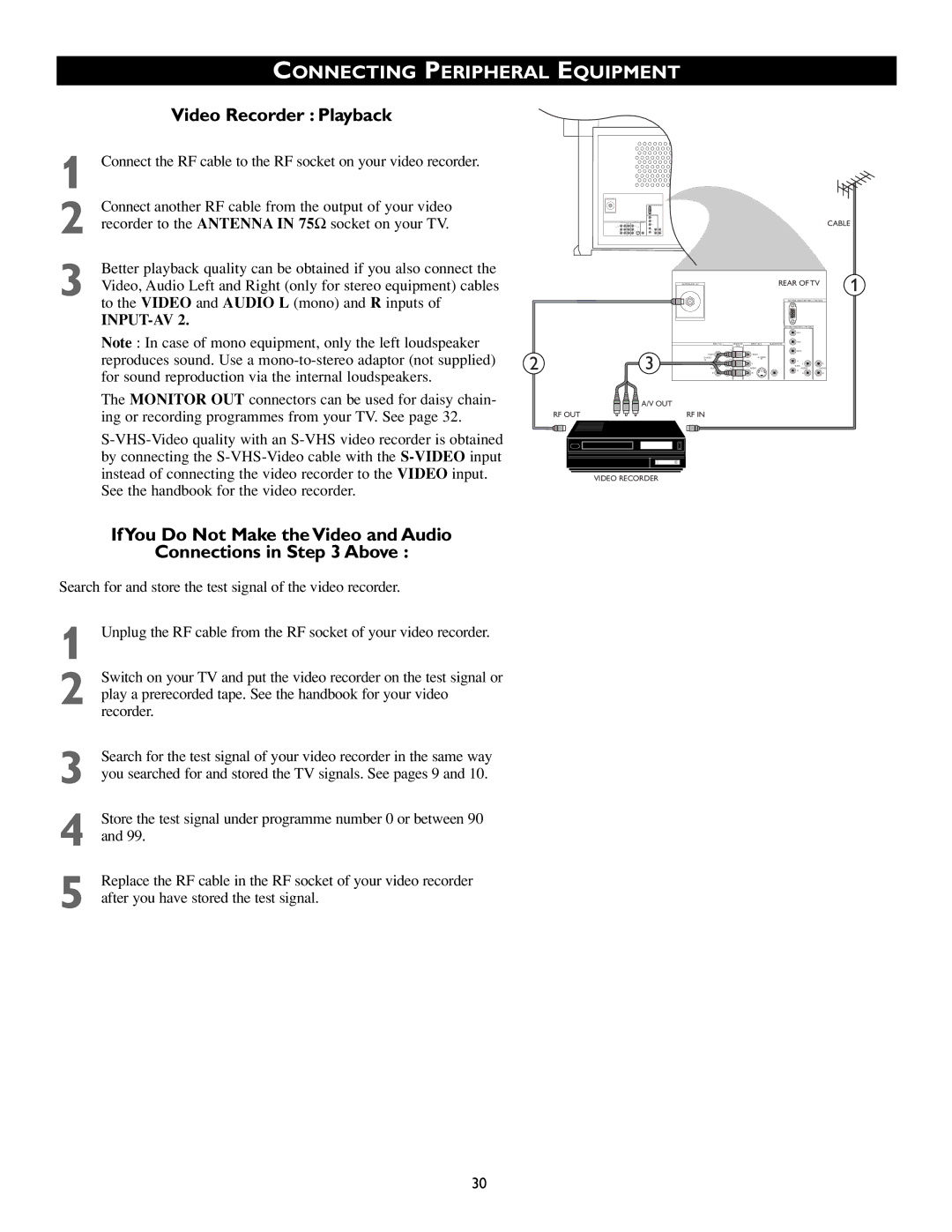
Connect the RF cable to the RF socket on your video recorder.
Connect another RF cable from the output of your video recorder to the ANTENNA IN 75Ω socket on your TV.
Better playback quality can be obtained if you also connect the Video, Audio Left and Right (only for stereo equipment) cables to the VIDEO and AUDIO L (mono) and R inputs of
INPUT-AV 2.
CABLE
ANTENNA IN 75Ω | REAR OF TV | 1 |
|
| |
|
| |
| G/Y |
|
Note : In case of mono equipment, only the left loudspeaker |
|
|
| Y |
|
| B/Pb |
| |
|
|
|
|
|
|
| R/Pr |
|
|
|
|
| MONITOR | SUBWOOFER |
|
| |||
|
|
|
| OUT |
|
|
|
|
|
reproduces sound. Use a | 2 | 3 | VIDEO |
| VIDEO |
| SYNC | L | L |
L |
| L | VIDEO | ||||||
| Pb | S- | L | V |
|
| |||
| L |
|
|
|
| ||||
for sound reproduction via the internal loudspeakers. | AUDIOR | Pr | AUDIOR |
| H | AUDIOR | AUDIOR | ||
|
|
|
|
|
|
|
|
| |
The MONITOR OUT connectors can be used for daisy chain- |
| A/V OUT |
|
|
|
|
|
|
|
ing or recording programmes from your TV. See page 32. | RF OUT |
| RF IN |
|
|
|
|
|
|
|
|
|
|
|
|
|
| ||
|
|
|
|
|
|
|
|
| |
by connecting the |
|
|
|
|
|
|
|
|
|
instead of connecting the video recorder to the VIDEO input. |
| VIDEO RECORDER |
|
|
|
|
|
|
|
See the handbook for the video recorder. |
|
|
|
|
|
|
|
|
|
If You Do Not Make the Video and Audio
Connections in Step 3 Above :
Search for and store the test signal of the video recorder.
1
Switch on your TV and put the video recorder on the test signal or
2 play a prerecorded tape. See the handbook for your video recorder.
3
4
5
Search for the test signal of your video recorder in the same way you searched for and stored the TV signals. See pages 9 and 10.
Store the test signal under programme number 0 or between 90 and 99.
Replace the RF cable in the RF socket of your video recorder after you have stored the test signal.
30