Connecting Accessory Devices to Your TV
CONNECTING AN HD RECEIVER TO THE HD INPUT-AV 5 JACKS
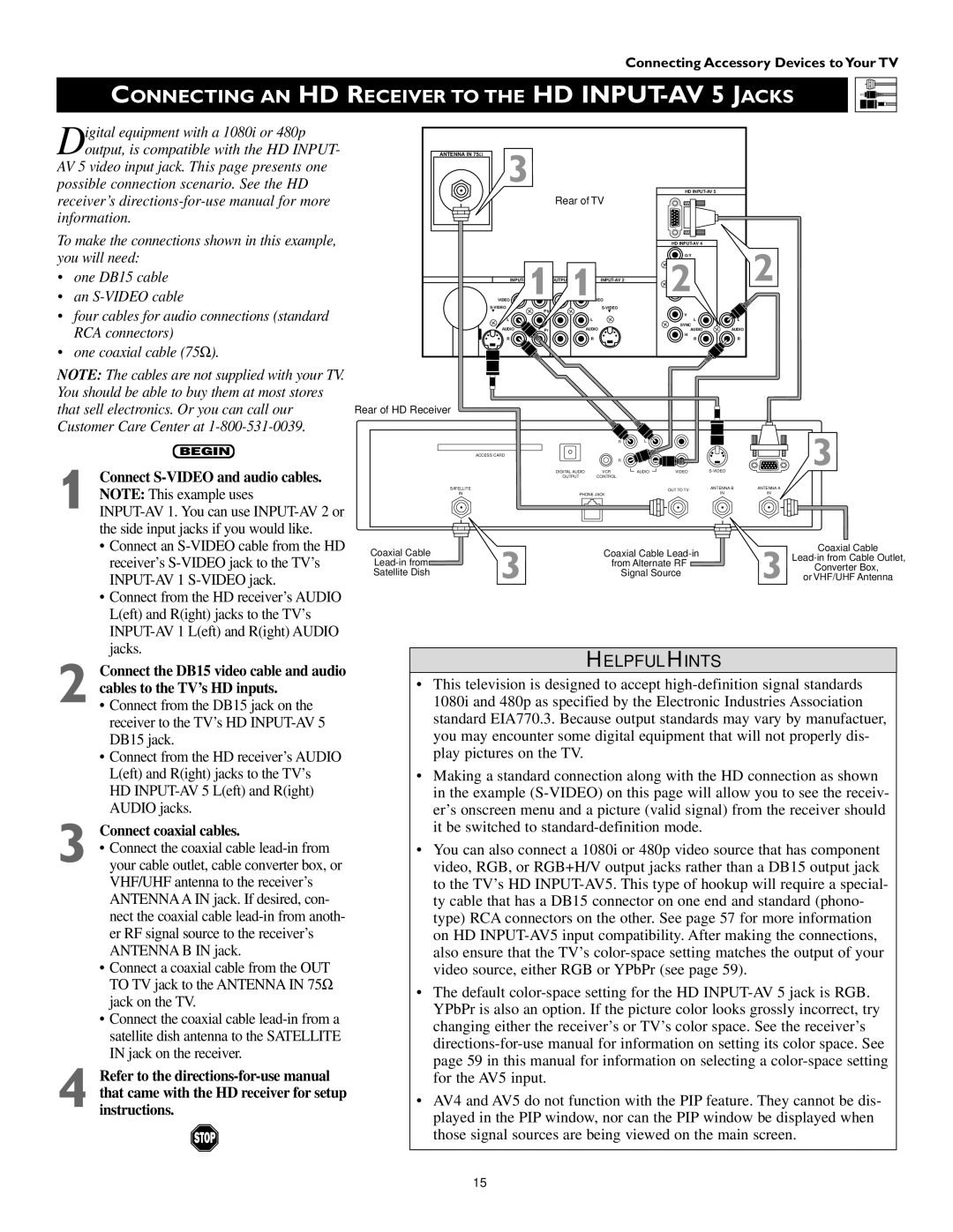
Digital equipment with a 1080i or 480p output, is compatible with the HD INPUT-
AV 5 video input jack. This page presents one possible connection scenario. See the HD receiver’s
To make the connections shown in this example, you will need:
•one DB15 cable
•an
•four cables for audio connections (standard RCA connectors)
•one coaxial cable (75Ω ).
ANTENNA IN 75Ω | 3 |
| HD |
| |
|
|
| Rear of TV |
|
|
|
|
|
| HD | 2 |
|
|
|
| G/Y | |
| INPUT- | 1 | 2 | ||
| VIDEO | 1VIDEO |
| ||
| Pb |
|
| ||
|
|
| V |
| |
|
|
|
|
| |
| L |
| L | L | L |
| AUDIO |
| AUDIO | SYNC |
|
| Pr | AUDIO | AUDIO | ||
| R |
|
| H |
|
|
| R | R | R | |
NOTE: The cables are not supplied with your TV. You should be able to buy them at most stores that sell electronics. Or you can call our Customer Care Center at
BEGIN
1 Connect S-VIDEO and audio cables. NOTE: This example uses
•Connect an
•Connect from the HD receiver’s AUDIO L(eft) and R(ight) jacks to the TV’s
2 Connect the DB15 video cable and audio cables to the TV’s HD inputs.
•Connect from the DB15 jack on the receiver to the TV’s HD
•Connect from the HD receiver’s AUDIO L(eft) and R(ight) jacks to the TV’s HD
3 | Connect coaxial cables. |
• Connect the coaxial cable | |
your cable outlet, cable converter box, or |
VHF/UHF antenna to the receiver’s ANTENNA A IN jack. If desired, con- nect the coaxial cable
• Connect a coaxial cable from the OUT TO TV jack to the ANTENNA IN 75Ω jack on the TV.
• Connect the coaxial cable
4 Refer to the
Rear of HD Receiver
|
| R | L |
|
| 3 |
| ACCESS CARD |
|
|
|
| |
|
| R |
|
|
| |
| DIGITAL AUDIO | VCR | AUDIO | VIDEO | ||
| OUTPUT | CONTROL |
|
|
|
|
SATELLITE |
|
|
| OUT TO TV | ANTENNA B | ANTENNA A |
IN | PHONE JACK |
|
| IN | IN | |
Coaxial Cable |
| Coaxial Cable |
| Coaxial Cable | ||
|
| |||||
| from Alternate RF |
| ||||
|
| Converter Box, | ||||
Satellite Dish |
|
| Signal Source |
| ||
3 |
|
| 3 or VHF/UHF Antenna | |||
|
|
|
|
| ||
HELPFUL HINTS
•This television is designed to accept
•Making a standard connection along with the HD connection as shown in the example
•You can also connect a 1080i or 480p video source that has component video, RGB, or RGB+H/V output jacks rather than a DB15 output jack to the TV’s HD
•The default
•AV4 and AV5 do not function with the PIP feature. They cannot be dis- played in the PIP window, nor can the PIP window be displayed when those signal sources are being viewed on the main screen.
15