|
|
| Connecting Accessory Devices to Your TV | |||
CONNECTING AN |
|
|
| |||
he |
|
|
|
|
|
|
Tside panel) of the TV can give you better pic- | ANTENNA IN 75Ω |
|
|
|
|
|
ture detail and clarity for the playback of |
|
|
|
|
|
|
VCR tapes or DVDs than the normal antenna |
|
|
|
| HD |
|
(RF signal) or Video (composite) picture connec- |
|
|
|
|
| |
|
| Rear of TV |
|
|
| |
tions. The example given connects a DVD/VCR |
|
|
|
|
|
|
Combi unit to the |
|
|
|
| HD |
|
of the TV. |
|
|
| 2 |
| |
|
|
| G/Y |
| ||
NOTE: The accessory device must have an |
|
| OUTPUT | R/Pr |
| |
| Y |
|
| B/Pb |
| |
|
|
|
|
|
| |
explained on this page. | VIDEO |
|
|
|
|
|
Pb |
| V |
| |||
|
|
|
|
|
| |
| L |
| L |
| L | L |
To make the connections, you will need: | R |
| R |
| SYNC | R |
|
| H R | ||||
| AUDIO | Pr | AUDIO |
| AUDIO | AUDIO |
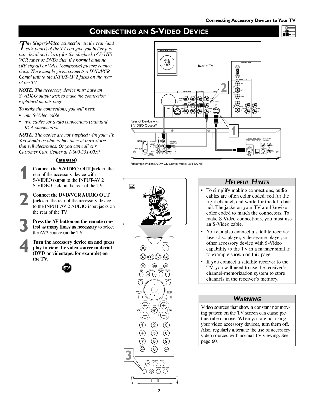
• one |
|
|
|
|
|
|
•two cables for audio connections (standard RCA connectors).
NOTE: The cables are not supplied with your TV. You should be able to buy them at most stores that sell electronics. Or you can call our Customer Care Center at
BEGIN
Rear of Device with | DVD/VCROUT | |
RAUDIOVIDEOL |
| |
| CH3CH4 |
|
1 | DIGITALAUDIOOUTCOMPNENT |
|
AUDIODVD/VCROUTLR | CbCr |
*(Example: Philips DVD/VCR Combi model DV910VHS)
1 Connect the
2 Connect the DVD/VCR AUDIO OUT jacks on the rear of the accessory device to the
3
4 Turn the accessory device on and press play to view the video source material (DVD or videotape, for example) on the TV.
AV2
POWER
TV | VCR | ACC |
|
| ACTIVE |
SWAP | PIP CH | CONTROL FREEZE |
DN | UP |
|
SOUND |
| PICTURE |
STATUS/ |
| MENU/ |
EXIT |
| SELECT |
| MUTE |
|
VOL |
| CH |
| 1 | 2 | 3 |
| 4 | 5 | 6 |
| 7 | 8 | 9 |
| TV/VCR | 0 |
|
3 | A/CH | SURF | |
SURF |
| PIP ON/OFF | |
REC • | FORMAT | SLEEP |
HELPFUL HINTS
•To simplify making connections, audio cables are often color coded: red for the right channel, and white for the left chan- nel. The jacks on your TV are likewise color coded to match the connectors. To make
•You can also connect a satellite receiver,
•If you connect a satellite receiver to the TV, you will need to use the receiver’s
WARNING
Video sources that show a constant nonmov- ing pattern on the TV screen can cause pic-
| SAP |
AV | DOLBY V PROG.LIST |
ITR/ | HOME |
| HOME PERSONAL |
RECORD | VIDEO |
| MOVIES |
|
|
|
|
13
