Connecting to the Network
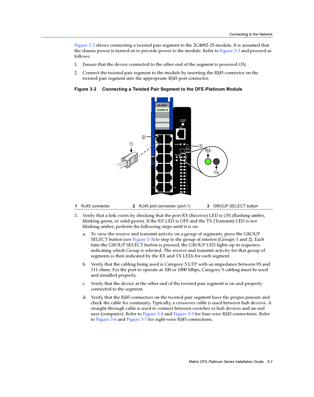
Figure 3‐3 shows connecting a twisted pair segment to the 2G4082‐25 module. It is assumed that the chassis power is turned on to provide power to the module. Refer to Figure 3‐3 and proceed as follows:
1.Ensure that the device connected to the other end of the segment is powered ON.
2.Connect the twisted pair segment to the module by inserting the RJ45 connector on the twisted pair segment into the appropriate RJ45 port connector.
Figure 3-3 Connecting a Twisted Pair Segment to the DFE-Platinum Module
Gb ENET
Á![]()
![]()
![]()
![]()
![]()
![]()
![]()
![]() À
À ![]()
![]()
![]()
![]()
![]()
1
11X
OFFLINE/
RESET
COM
MGMT | CPU | Â |
| GROUP |
|
| SELECT |
|
GROUP
1 ![]()
![]()
![]() 1
1
2 ![]()
![]()
![]() 2
2
![]()
![]() 3
3
![]()
![]() 4
4
![]()
![]() 5
5
![]()
![]() 6
6
![]()
![]() 7
7
![]()
![]() 8
8
![]()
![]() 9
9 ![]()
![]() 10
10
12X
11
![]()
![]() 12
12
RX
TX
1 RJ45 connector | 2 RJ45 port connector (port 1) | 3 GROUP SELECT button |
3.Verify that a link exists by checking that the port RX (Receive) LED is ON (flashing amber, blinking green, or solid green). If the RX LED is OFF and the TX (Transmit) LED is not blinking amber, perform the following steps until it is on:
a.To view the receive and transmit activity on a group of segments, press the GROUP SELECT button (see Figure 3‐3) to step to the group of interest (Groups 1 and 2). Each time the GROUP SELECT button is pressed, the GROUP LED lights up in sequence, indicating which Group is selected. The receive and transmit activity for that group of segments is then indicated by the RX and TX LEDs for each segment.
b.Verify that the cabling being used is Category 5 UTP with an impedance between 85 and 111 ohms. For the port to operate at 100 or 1000 Mbps, Category 5 cabling must be used and installed properly.
c.Verify that the device at the other end of the twisted pair segment is on and properly connected to the segment.
d.Verify that the RJ45 connectors on the twisted pair segment have the proper pinouts and check the cable for continuity. Typically, a crossover cable is used between hub devices. A straight‐through cable is used to connect between switches or hub devices and an end user (computer). Refer to Figure 3‐4 and Figure 3‐5 for four‐wire RJ45 connections. Refer to Figure 3‐6 and Figure 3‐7 for eight‐wire RJ45 connections.
Matrix