Installing Module into Matrix E7 or N7 Chassis
Caution: In step 4, do not force the locking levers to the point that they touch the face of the front panel. Forcing the locking levers to this point could damage the module and chassis.
Precaución: En el paso 4, tenga cuidado de no llevar las palancas de cierre a un punto en donde estén en contacto con el panel frontal. Si lo hace, podría dañar el módulo y/o el chasis.
4.Refer to the Caution note above, then rotate the two levers into the closed position.
5.If the chassis in which the module is installed was powered down for the installation, turn the power supplies on. Check to see that the module CPU LED settles at solid green after a few minutes. If the LED does not turn solid green, refer to Chapter 4 for troubleshooting details.
Caution: When setting the locking levers to the closed position, do not try to force the locking levers to the point that they touch the face of the front panel. Forcing the locking levers to this point could damage the module and chassis.
Precaución: Al mover las palancas a la posición de cerrado, tenga cuidado de no llevarlas a un punto en donde estén en contacto con el panel frontal. Si lo hace, podría dañar el módulo o el chasis.
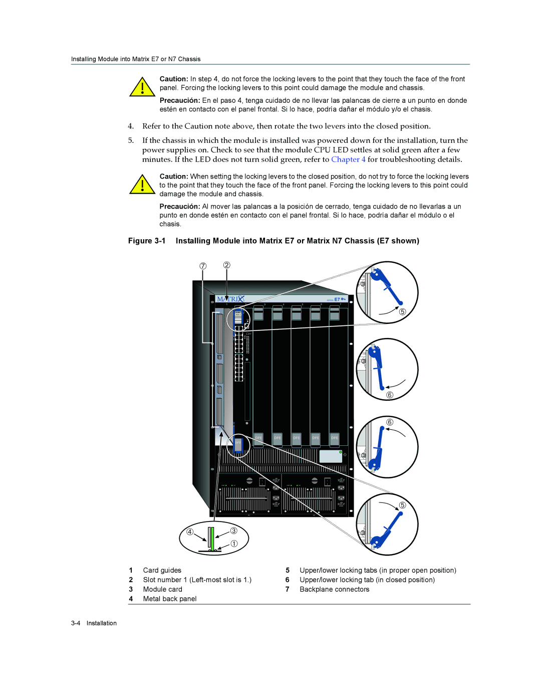
Figure 3-1 Installing Module into Matrix E7 or Matrix N7 Chassis (E7 shown)
ÆÁ
SERIES E7 ![]()
1 | 2 | 3 | 4 | 5 | 6 | 7 |
| Gb ENET |
|
|
|
| Ä |
|
|
|
|
| ||
|
|
|
|
|
| Å |
|
|
|
|
|
| Å |
| DFE |
|
|
|
|
|
|
|
| LINE |
|
| LINE |
|
| ACON1 |
| ACON1 | ||
|
|
| ||||
|
|
| 50/60Hz |
|
| 50/60Hz |
|
| 0 |
|
| 0 |
|
POWER | FAN | POWER | FAN |
LINE
PS1
Ã![]()
![]()
![]() Â
Â
![]()
![]() À
À
LINE | Ä |
| |
| |
50/60Hz |
|
PS2
1 | Card guides | 5 | Upper/lower locking tabs (in proper open position) |
2 | Slot number 1 | 6 | Upper/lower locking tab (in closed position) |
3 | Module card | 7 | Backplane connectors |
4Metal back panel