Memory Locations and Replacement Procedures
Location of Memory Modules
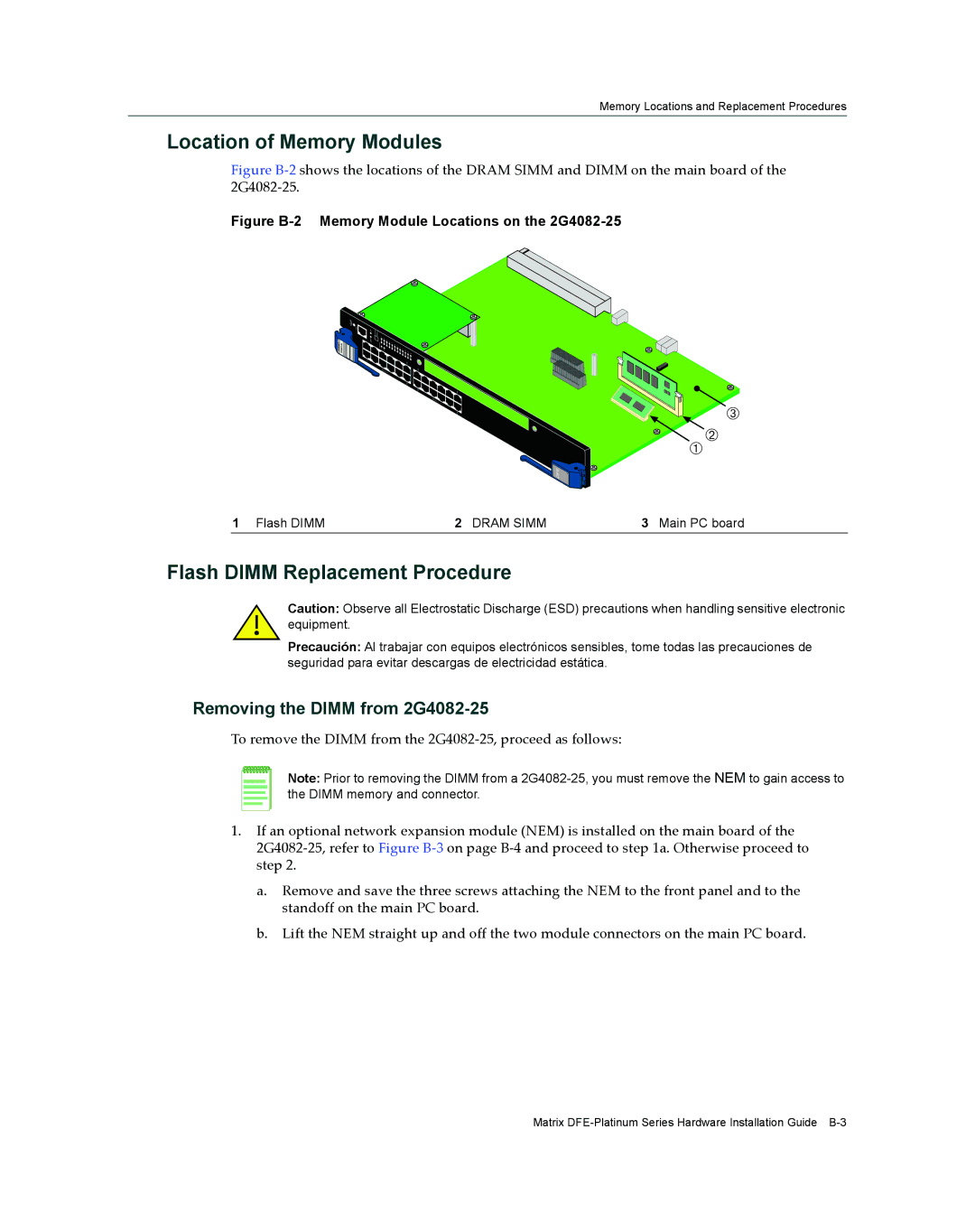
Figure B‐2 shows the locations of the DRAM SIMM and DIMM on the main board of the 2G4082‐25.
Figure B-2 Memory Module Locations on the 2G4082-25
ENETGb
G2 04 28 52-
![]()
![]() Â
 ![]() ÀÁ
ÀÁ
![]() DFE
DFE
1 Flash DIMM | 2 DRAM SIMM | 3 Main PC board |
Flash DIMM Replacement Procedure
Caution: Observe all Electrostatic Discharge (ESD) precautions when handling sensitive electronic equipment.
Precaución: Al trabajar con equipos electrónicos sensibles, tome todas las precauciones de seguridad para evitar descargas de electricidad estática.
Removing the DIMM from 2G4082-25
To remove the DIMM from the 2G4082‐25, proceed as follows:
Note: Prior to removing the DIMM from a
1.If an optional network expansion module (NEM) is installed on the main board of the 2G4082‐25, refer to Figure B‐3 on page B‐4 and proceed to step 1a. Otherwise proceed to step 2.
a.Remove and save the three screws attaching the NEM to the front panel and to the standoff on the main PC board.
b.Lift the NEM straight up and off the two module connectors on the main PC board.
Matrix