Memory Locations and Replacement Procedures
•Switch 8 – Clear Admin Password. Changing the position of this switch clears the admin password, and restores the factory default password on the next power‐up of the module. Once the module resets, you can either use the factory default settings or reenter your own password.
Note: Do not change the position of Switch 8 unless it is necessary to reset the admin password to its factory default setting.
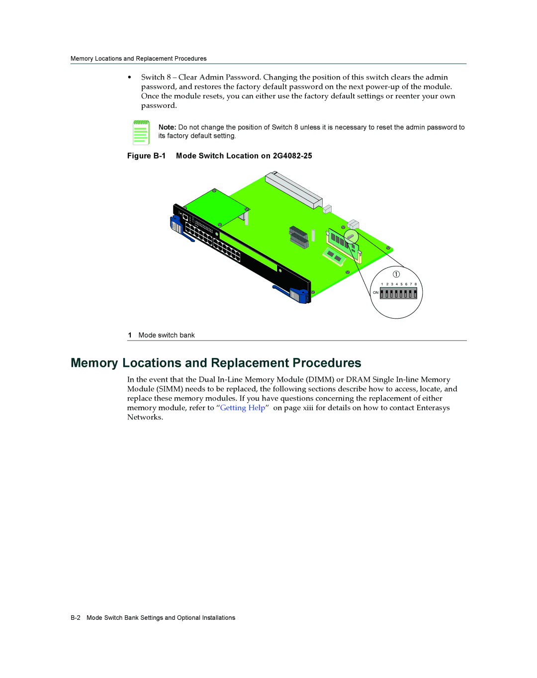
Figure B-1 Mode Switch Location on 2G4082-25
ENETGb
G2 04 28 52-
![]() DFE
DFE
À
1 2 3 4 5 6 7 8 ON ![]()
![]()
![]()
![]()
![]()
![]()
![]()
![]()
![]()
![]()
![]()
![]()
![]()
![]()
![]()
![]()
![]()
![]()
1Mode switch bank
Memory Locations and Replacement Procedures
In the event that the Dual In‐Line Memory Module (DIMM) or DRAM Single In‐line Memory Module (SIMM) needs to be replaced, the following sections describe how to access, locate, and replace these memory modules. If you have questions concerning the replacement of either memory module, refer to “Getting Help” on page xiii for details on how to contact Enterasys Networks.