Connecting to the Network
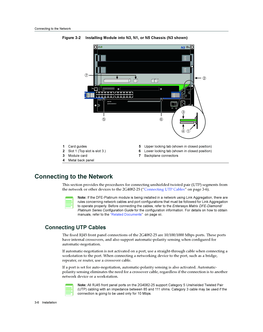
Figure 3-2 Installing Module into N3, N1, or N5 Chassis (N3 shown)
|
|
| FAN |
|
|
|
|
|
|
|
|
|
|
|
|
|
|
|
| STATUS |
|
|
|
|
|
|
|
|
|
|
|
|
|
Æ |
|
|
|
|
|
|
|
|
|
|
|
|
|
| Á | |
|
|
|
|
|
|
|
|
|
|
|
|
|
|
|
| |
| OFFLINE/ RESET | COM | 7C203CPU GROUP | 1 | 2 | 3 | 4 | 5 | 6 | 7 8 9 10 | 11 12 | 14X |
| 24X |
| |
| MGMT |
| GROUP 1 | 2 |
|
|
|
| REDUNDANCY12X |
|
| |||||
|
|
|
|
|
|
|
|
|
|
| PWR |
|
|
|
|
|
GbENET |
|
|
|
|
|
|
|
|
|
|
|
|
| DFE | 240V~6.0A | |
|
|
|
|
|
|
|
|
|
|
|
|
|
|
|
| 125V~12.0A |
|
|
|
|
|
|
|
| 1 |
|
|
| 11X | 13X | G R O U P 2 | 23X | 50/60 Hz |
|
|
|
|
|
|
|
|
|
|
|
|
|
|
| ||
|
|
|
|
|
|
|
|
|
|
| PWR |
|
|
|
|
|
|
|
|
|
|
|
|
|
|
|
| REDUNDANCY |
|
|
|
| |
|
|
|
|
|
|
|
|
|
|
|
|
|
|
| 0 | |
|
|
|
|
|
|
|
|
|
|
|
|
|
|
|
| |
|
|
|
|
|
|
|
|
|
|
|
|
|
|
|
| Â |
|
|
|
|
|
|
|
|
|
|
|
|
|
|
|
| 50/60 Hz |
|
|
|
| Ä |
|
|
|
|
|
|
| Å |
| |||
|
|
|
|
|
|
|
|
|
|
|
|
|
|
|
| Ã À |
1 | Card guides | 5 | Upper locking tab (shown in closed position) |
2 | Slot 1 (Top slot is slot 3.) | 6 | Lower locking tab (shown in closed position) |
3 | Module card | 7 | Backplane connectors |
4Metal back panel
Connecting to the Network
This section provides the procedures for connecting unshielded twisted pair (UTP) segments from the network or other devices to the 2G4082‐25 (“Connecting UTP Cables” on page 3‐6).
Note: If the
Connecting UTP Cables
The fixed RJ45 front panel connections of the 2G4082‐25 are 10/100/1000 Mbps ports. These ports have internal crossovers, and also support automatic‐polarity sensing when configured for automatic‐negotiation.
If automatic‐negotiation is not activated on a port, use a straight‐through cable when connecting a workstation to the port. When connecting a networking device to the port, such as a bridge, repeater, or router, use a crossover cable.
If a port is set for auto‐negotiation, automatic‐polarity sensing is also activated. Automatic‐ polarity sensing eliminates the need for a crossover cable, regardless if the connection is to another network device or a workstation.
Note: All RJ45 front panel ports on the