Memory Locations and Replacement Procedures
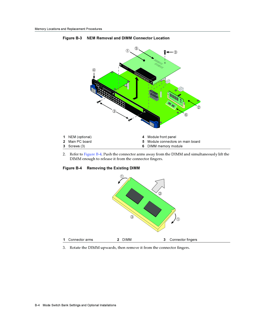
Figure B-3 NEM Removal and DIMM Connector Location
Ã
ENETGb | 52- 280 4G |
| 2 |
À | Ä | Â |
|
| |
1 |
|
|
2 |
|
|
3 |
|
|
4 |
|
|
5 |
|
|
6 |
|
|
|
| |
6MGBIC- |
|
|
7G | 1 |
|
| 2 |
|
|
| 3 |
|
| 4 |
|
| 5 |
|
| 6 |
 | Á | |
Å | ||
| ||
| DFE |
1 | NEM (optional) | 4 | Module front panel |
2 | Main PC board | 5 | Module connectors on main board |
3 | Screws (3) | 6 | DIMM memory module |
2.Refer to Figure B‐4. Push the connector arms away from the DIMM and simultaneously lift the DIMM enough to release it from the connector fingers.
Figure B-4 Removing the Existing DIMM
À
Á
 ![]()
![]()
![]()
![]()
![]()
![]()
![]()
![]()
 À
À
1 Connector arms | 2 DIMM | 3 Connector fingers |
3.Rotate the DIMM upwards, then remove it from the connector fingers.
