USING THE AUDIO/VIDEO INPUT JACKS (CONTINUED)
COMPONENT VIDEO INPUTS
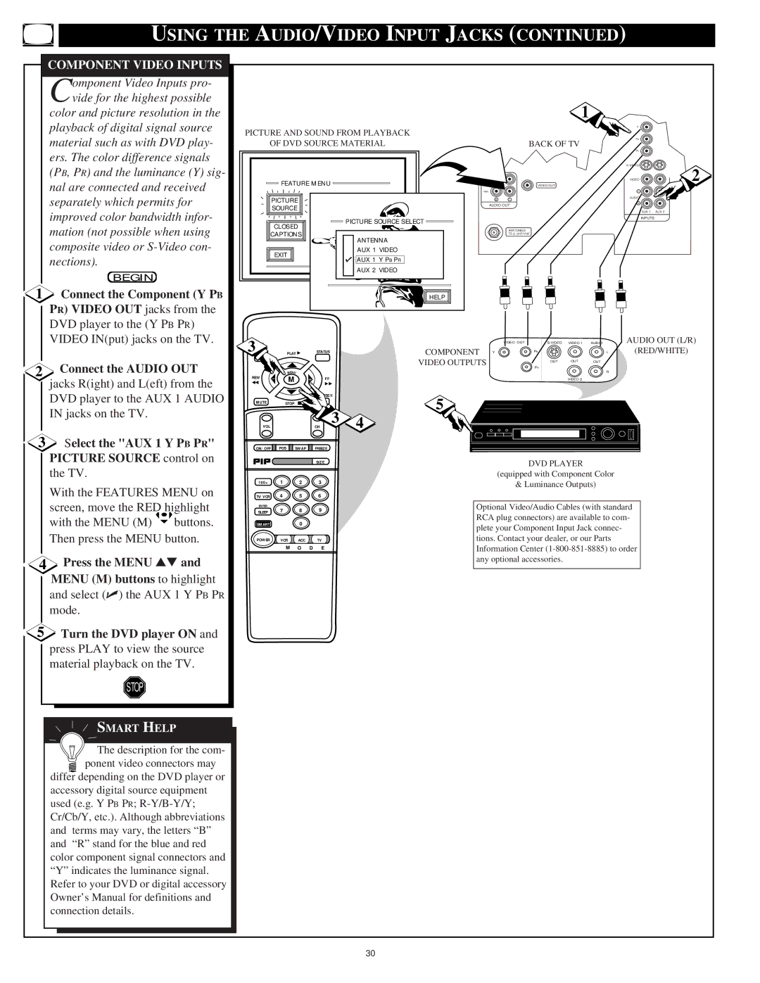
Component Video Inputs pro- vide for the highest possible
color and picture resolution in the playback of digital signal source material such as with DVD play- ers. The color difference signals (PB, PR) and the luminance (Y) sig- nal are connected and received separately which permits for improved color bandwidth infor- mation (not possible when using composite video or
BEGIN
1 Connect the Component (Y PB |
PR) VIDEO OUT jacks from the |
DVD player to the (Y PB PR) |
PICTURE AND SOUND FROM PLAYBACK
OF DVD SOURCE MATERIAL
FEATURE MENU |
| |
PICTURE | CABLE | |
SOURCE | TUNING | |
PICTURE SOURCE SELECT | ||
CLOSED | CHANNEL | |
CAPTIONS | ANTENNA | |
| ||
EXIT | AUX 1 VIDEO | |
AUX 1 Y PB PR | ||
| ||
| AUX 2 VIDEO | |
EXIT | HELP | |
1
|
| Y |
|
|
| PB |
|
|
| BACK OF TV |
|
|
| PR |
|
|
| 2 | |
FIXED |
| VIDEO | |
|
| VIDEO OUT |
|
VAR |
| L |
|
R | L | AUDIO |
|
|
| ||
AUDIO OUT | R |
| |
|
| ||
|
| AUX 1 | AUX 2 |
|
| INPUTS |
|
ANT/CABLE
75 V UHF/VHF
VIDEO IN(put) jacks on the TV. |
2 Connect the AUDIO OUT |
jacks R(ight) and L(eft) from the |
DVD player to the AUX 1 AUDIO |
IN jacks on the TV. |
3Select the "AUX 1 Y PB PR" PICTURE SOURCE control on the TV.
With the FEATURES MENU on screen, move the RED highlight
with the MENU (M) ![]() buttons. Then press the MENU button.
buttons. Then press the MENU button.
4Press the MENU ▲▼ and MENU (M) buttons to highlight and select (✔) the AUX 1 Y PB PR mode.
5Turn the DVD player ON and press PLAY to view the source material playback on the TV.
STOP
SMART HELP
 The description for the com- ponent video connectors may
differ depending on the DVD player or accessory digital source equipment used (e.g. Y PB PR;
3 ● |
| PLAY ▶ | STATUS |
| |
CLEAR |
|
|
|
|
|
REW |
| MENU |
|
|
|
− | M | + | FF |
| |
◀◀ |
| ||||
|
|
| ▶▶ |
| |
|
|
| PAUSE II |
| |
MUTE |
| STOP ■ | SURF |
| |
VOL |
|
| CH | 3 | 4 |
|
|
| |||
ON/OFF ![]()
![]() POS
POS ![]()
![]() SWAP
SWAP ![]()
![]() FREEZE
FREEZE
SIZE
100+ 1 2 3
TV/VCR 4 5 6
ENTER
SLEEP 7 8 9
SMART0
POWER VCR ACC TV
M O D E
VIDEO OUT | VIDEO 1 | AUDIO | AUDIO OUT (L/R) | |
COMPONENT Y | PB |
| L | (RED/WHITE) |
VIDEO OUTPUTS | OUT | OUT | OUT |
|
| PR |
|
|
|
|
|
| R |
|
|
| VIDEO 2 |
|
|
5
DVD PLAYER
(equipped with Component Color
& Luminance Outputs)
Optional Video/Audio Cables (with standard RCA plug connectors) are available to com- plete your Component Input Jack connec- tions. Contact your dealer, or our Parts Information Center
30