User Manual BDL6531E
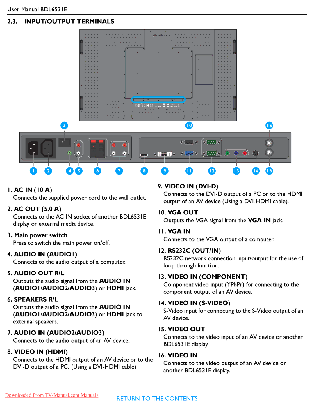
2.3.INPUT/OUTPUT TERMINALS
|
| 3 |
|
|
|
|
| 10 |
|
|
| 15 |
1 | 2 | 4 | 5 | 6 | 7 | 8 | 9 | 11 | 12 | 13 | 14 | 16 |
1. AC IN (10 A)
Connects the supplied power cord to the wall outlet.
2. AC OUT (5.0 A)
Connects to the AC IN socket of another BDL6531E display or external media device.
3. Main power switch
Press to switch the main power on/off.
4. AUDIO IN (AUDIO1)
Connects to the audio output of a computer.
5. AUDIO OUT R/L
Outputs the audio signal from the AUDIO IN
(AUDIO1/AUDIO2/AUDIO3) or HDMI jack.
6. SPEAKERS R/L
Outputs the audio signal from the AUDIO IN
(AUDIO1/AUDIO2/AUDIO3) or HDMI jack to external speakers.
7.AUDIO IN (AUDIO2/AUDIO3) Connects to the audio output of an AV device.
8.VIDEO IN (HDMI)
Connects to the HDMI output of an AV device or to the
9. VIDEO IN (DVI-D)
Connects to the
10. VGA OUT
Outputs the VGA signal from the VGA IN jack.
11. VGA IN
Connects to the VGA output of a computer.
12. RS232C (OUT/IN)
RS232C network connection input/output for the use of loop through function.
13. VIDEO IN (COMPONENT)
Component video input (YPbPr) for connecting to the component output of an AV device.
14. VIDEO IN (S-VIDEO)
15. VIDEO OUT
Connects to the video input of an AV device or another BDL6531E display.
16. VIDEO IN
Connects to the video output of an AV device or another BDL6531E display.
Downloaded From
RETURN TO THE CONTENTS
