AAM Loop Antenna
Connection
Connect the supplied loop antenna to the AM ANTENNA terminal. Place the AM loop antenna far away from the system and adjust its position for the best reception.
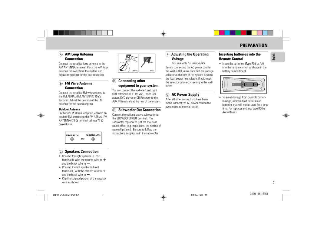
12 mm![]()
unlock
lock
FAdjusting the Operating
Voltage
(not available for version /30)
Before connecting the AC power cord to the wall outlet, make sure that the voltage selector at the rear of the system is set to the local power line voltage. If not, reset
PREPARATION
Inserting batteries into the | English |
Remote Control |
•Insert the batteries (Type R06 or AA) into the remote control as shown in the battery compartment.
BFM Wire Antenna
Connection
Connect the supplied FM wire antenna to the FM AERIAL (FM ANTENNA) 75 Ω terminal. Adjust the position of the FM antenna for the best reception.
Outdoor Antenna
For better FM stereo reception, connect an outdoor FM antenna to the FM AERIAL (FM ANTENNA) 75 Ω terminal using a 75 Ω coaxial wire.
FM AERIAL 75Ω | FM ANTENNA 75Ω |
OR
DConnecting other
equipment to your system
You can connect the audio left and right OUT terminals of a TV, VCR, Laser Disc player, DVD player or CD Recorder to the AUX IN terminals at the rear of the system.
ESubwoofer Out Connection
Connect the optional active subwoofer to the SUBWOOFER OUT terminal. The subwoofer reproduces just the low bass sound effect (e.g. explosions, the rumble of spaceships, etc.). Be sure to follow the instructions supplied with the subwoofer.
the selector before connecting to the wall outlet.
GAC Power Supply
After all other connections have been made, connect the AC power cord to the system and to the wall outlet.
- | + | - | + |
•To avoid damage from possible battery leakage, remove dead batteries or batteries that will not be used for a long time. For replacement, use type R06 or AA batteries.
CSpeakers Connection
•Connect the right speaker to Front terminal R, with the colored wire to + and the black wire to
•Connect the left speaker to Front terminal L, with the colored wire to + and the black wire to
•Clip the stripped portion of the speaker wire as shown.
pg | 7 | 3/3/00, 4:23 PM |
7