Philips Semiconductors | ISP1301 USB OTG Transceiver Eval Kit User’s Guide |
|
|
|
| J6 | J7 |
|
|
| J10 |
|
|
|
|
|
|
|
| J 2 |
|
|
| JP3 | JP4 | J11 | JP1 |
|
|
|
|
|
| |||
J12 | JP5 | JP2 |
|
|
|
|
|
|
|
|
| J | J9 |
| J8 | J3 |
| U1 | 5 | |
|
|
| ||||
|
|
|
|
| ||
|
|
| SW1 |
|
| J1 |
|
|
|
|
|
| |
J13 |
|
|
|
|
|
|
|
|
|
|
| JP6 | J4 |
|
| U4 |
|
|
| |
|
|
|
|
|
| |
|
|
|
| ISP1301 EVALUATION BOARD |
| |
|
|
|
| REV 1.0 |
|
|
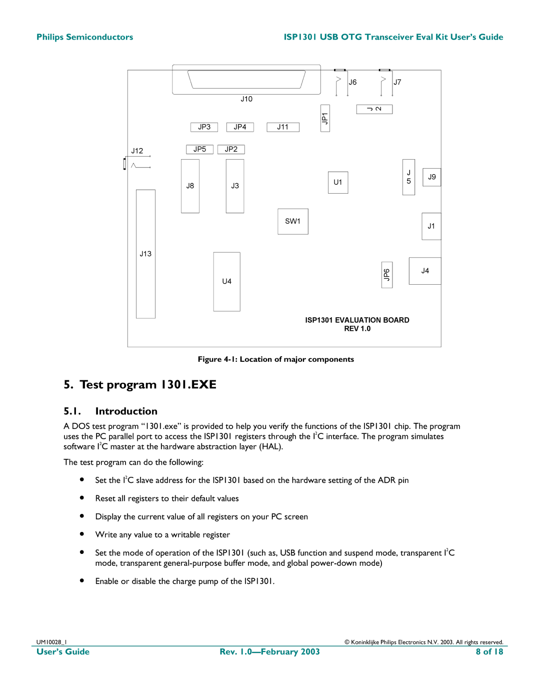
Figure 4-1: Location of major components
5. Test program 1301.EXE
5.1.Introduction
A DOS test program “1301.exe” is provided to help you verify the functions of the ISP1301 chip. The program uses the PC parallel port to access the ISP1301 registers through the I2C interface. The program simulates software I2C master at the hardware abstraction layer (HAL).
The test program can do the following:
•Set the I2C slave address for the ISP1301 based on the hardware setting of the ADR pin
•Reset all registers to their default values
•Display the current value of all registers on your PC screen
•Write any value to a writable register
•Set the mode of operation of the ISP1301 (such as, USB function and suspend mode, transparent I2C mode, transparent
•Enable or disable the charge pump of the ISP1301.
UM10028_1 |
| © Koninklijke Philips Electronics N.V. 2003. All rights reserved. |
User’s Guide | Rev. | 8 of 18 |
