Philips Semiconductors | ISP1301 USB OTG Transceiver Eval Kit User’s Guide |
6. Hardware description
6.1.Block diagram
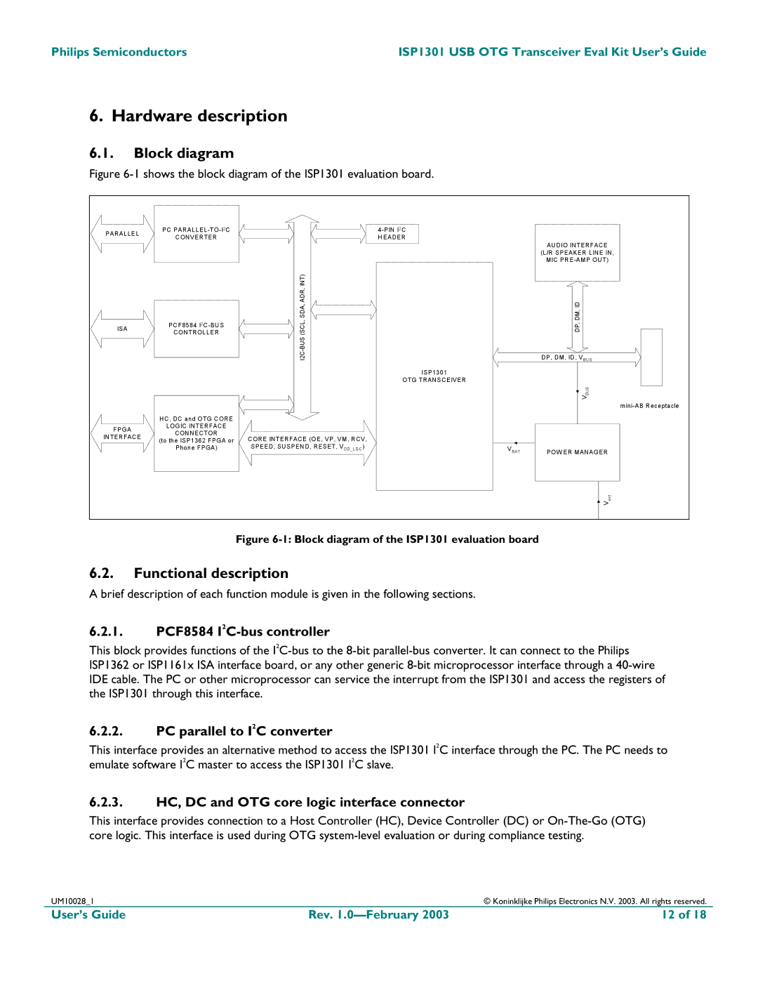
Figure 6-1 shows the block diagram of the ISP1301 evaluation board.
PARALLEL | PC |
|
| |
CONVERTER |
| HEADER |
| |
|
|
| ||
|
|
|
| AUDIO INTERFACE |
|
|
|
| (L/R SPEAKER LINE IN, |
|
|
|
| MIC |
|
| INT) |
|
|
ISA | PCF8584 | (SCL, SDA, ADR, |
| DP, DM, ID |
CONTROLLER |
| |||
|
|
| DP, DM, ID, VBUS | |
|
|
| ISP1301 |
|
|
|
| OTG TRANSCEIVER |
|
|
|
|
| BUS |
|
|
|
| V |
|
|
|
| |
| HC, DC and OTG CORE |
|
|
|
FPGA | LOGIC INTERFACE |
|
|
|
CONNECTOR |
|
|
| |
INTERFACE | CORE INTERFACE (OE, VP, VM, RCV, |
|
| |
(to the ISP1362 FPGA or |
|
| ||
|
|
| ||
| Phone FPGA) | SPEED, SUSPEND, RESET, VDD_LGC) | VBAT | POW ER MANAGER |
|
|
| ||
|
|
|
| ext |
|
|
|
| V |
Figure 6-1: Block diagram of the ISP1301 evaluation board
6.2.Functional description
A brief description of each function module is given in the following sections.
6.2.1.PCF8584 I2C-bus controller
This block provides functions of the
6.2.2.PC parallel to I2C converter
This interface provides an alternative method to access the ISP1301 I2C interface through the PC. The PC needs to emulate software I2C master to access the ISP1301 I2C slave.
6.2.3.HC, DC and OTG core logic interface connector
This interface provides connection to a Host Controller (HC), Device Controller (DC) or
UM10028_1 |
| © Koninklijke Philips Electronics N.V. 2003. All rights reserved. |
User’s Guide | Rev. | 12 of 18 |
