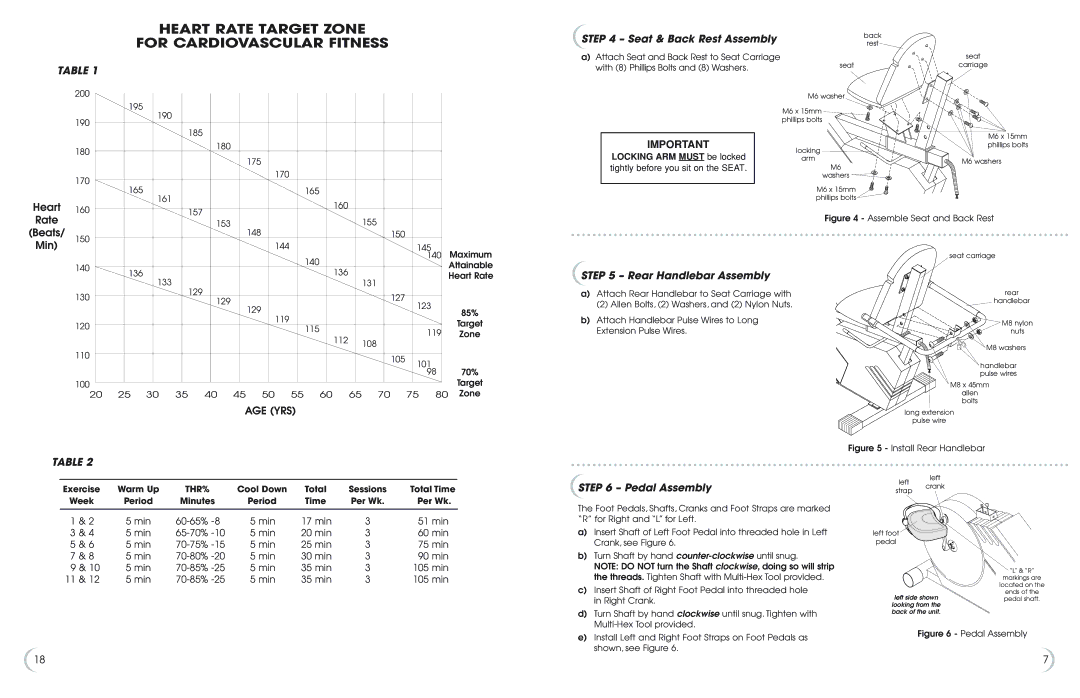
HEART RATE TARGET ZONE
FOR CARDIOVASCULAR FITNESS
STEP 4 – Seat & Back Rest Assembly | back |
rest |
a)Attach Seat and Back Rest to Seat Carriage
seat
TABLE 1
200
with (8) Phillips Bolts and (8) Washers. | seat |
| M6 washer |
carriage
190
180
170
195 | 190 |
| |
|
|
| 185 |
| 180 |
| 175 |
| 170 |
165 | 165 |
| 161 |
IMPORTANT
LOCKING ARM MUST be locked
tightly before you sit on the SEAT.
M6 x 15mm ![]()
![]() phillips bolts
phillips bolts
locking
arm
M6 washers ![]()
M6 x 15mm ![]() phillips bolts
phillips bolts ![]()
M6 x 15mm phillips bolts
M6 washers
Heart 160 Rate
(Beats/
| 160 |
157 | 155 |
153 | |
148 | 150 |
Figure 4 - Assemble Seat and Back Rest
Min)
150
140
130
120
110
100
20
|
|
|
|
|
| 144 |
|
|
|
| 145 | Maximum | |
|
|
|
|
|
|
| 140 |
|
|
|
| 140 | |
136 |
|
|
|
|
|
| 136 |
|
|
|
| Attainable | |
133 |
|
|
|
|
|
| 131 |
|
|
| Heart Rate | ||
|
| 129 |
|
|
|
|
|
|
|
|
| ||
|
|
|
|
|
|
|
|
| 127 |
|
|
| |
|
|
| 129 |
|
|
|
|
|
| 123 |
| ||
|
|
|
| 129 |
|
|
|
|
|
| |||
|
|
|
|
|
|
|
|
|
| 85% | |||
|
|
|
|
| 119 |
|
|
|
|
|
| ||
|
|
|
|
|
|
|
|
|
|
|
| ||
|
|
|
|
|
| 115 |
|
|
|
|
| Target | |
|
|
|
|
|
|
|
|
|
|
| 119 | ||
|
|
|
|
|
|
|
|
|
|
| Zone | ||
|
|
|
|
|
|
|
| 112 | 108 |
|
| ||
|
|
|
|
|
|
|
|
|
|
|
| ||
|
|
|
|
|
|
|
|
|
|
|
|
| |
|
|
|
|
|
|
|
|
|
| 105 | 101 |
| |
|
|
|
|
|
|
|
|
|
|
| 70% | ||
|
|
|
|
|
|
|
|
|
|
|
| 98 | |
|
|
|
|
|
|
|
|
|
|
|
|
| Target |
25 | 30 | 35 | 40 | 45 | 50 | 55 | 60 | 65 | 70 |
| 75 | 80 | Zone |
AGE (YRS)
STEP 5 – Rear Handlebar Assembly
a)Attach Rear Handlebar to Seat Carriage with
(2) Allen Bolts, (2) Washers, and (2) Nylon Nuts.
b)Attach Handlebar Pulse Wires to Long Extension Pulse Wires.
seat carriage
rear
handlebar
M8 nylon
nuts ![]() M8 washers
M8 washers
handlebar pulse wires
M8 x 45mm
allen bolts
long extension
pulse wire
Figure 5 - Install Rear Handlebar
TABLE 2
left
left
| Exercise | Warm Up | THR% | Cool Down | Total | Sessions | Total Time | |
| Week | Period | Minutes | Period | Time | Per Wk. | Per Wk. | |
|
|
|
|
|
|
|
|
|
&1 | & 2 | 5 min | 5 min | 17 min | 3 | 51 min | ||
&3 | & 4 | 5 min | 5 min | 20 min | 3 | 60 min | ||
&5 | & 6 | 5 min | 5 min | 25 min | 3 | 75 min | ||
&7 | & 8 | 5 min | 5 min | 30 min | 3 | 90 min | ||
& 9 & 10 | 5 min | 5 min | 35 min | 3 | 105 min | |||
&11 | & 12 | 5 min | 5 min | 35 min | 3 | 105 min | ||
STEP 6 – Pedal Assembly
The Foot Pedals, Shafts, Cranks and Foot Straps are marked “R” for Right and “L” for Left.
a) Insert Shaft of Left Foot Pedal into threaded hole in Left |
Crank, see Figure 6. |
b) Turn Shaft by hand |
NOTE: DO NOT turn the Shaft clockwise, doing so will strip |
the threads. Tighten Shaft with |
c) Insert Shaft of Right Foot Pedal into threaded hole |
strap
left foot
pedal
crank
“L” & “R”
markings are
located on the
ends of the
| in Right Crank. |
d) | Turn Shaft by hand clockwise until snug. Tighten with |
| |
e) | Install Left and Right Foot Straps on Foot Pedals as |
| shown, see Figure 6. |
left side shownpedal shaft. looking from the
back of the unit.
Figure 6 - Pedal Assembly
18 | 7 |
