INSTALLATION

1.8.3.PILOT FLAME ADJUSTMENT Perform this procedure with the pilot lit.

Note: This procedure requires the use of a DC microammeter.

1.Connect the DC microammeter between the flame sensor terminal and the flame sensor lead. Observe proper polarity: if the meter needle goes below 0, reverse the leads. The current reading must be 1.0 μA or greater, (0.15 μA or greater for CE units).

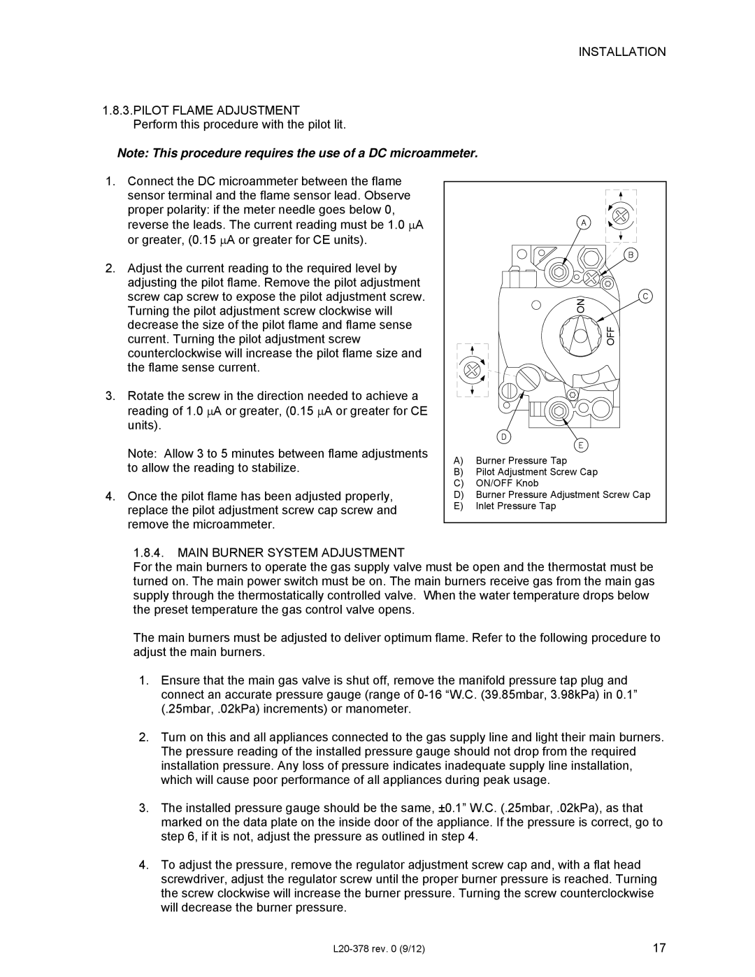
2.Adjust the current reading to the required level by adjusting the pilot flame. Remove the pilot adjustment screw cap screw to expose the pilot adjustment screw. Turning the pilot adjustment screw clockwise will decrease the size of the pilot flame and flame sense current. Turning the pilot adjustment screw counterclockwise will increase the pilot flame size and the flame sense current.

3.Rotate the screw in the direction needed to achieve a reading of 1.0 μA or greater, (0.15 μA or greater for CE units).

Note: Allow 3 to 5 minutes between flame adjustments to allow the reading to stabilize.

4.Once the pilot flame has been adjusted properly, replace the pilot adjustment screw cap screw and remove the microammeter.


NO


OFF

A)

Burner Pressure Tap

B) Pilot Adjustment Screw Cap

C)

ON/OFF Knob

D) Burner Pressure Adjustment Screw Cap

E)

Inlet Pressure Tap

1.8.4.MAIN BURNER SYSTEM ADJUSTMENT

For the main burners to operate the gas supply valve must be open and the thermostat must be turned on. The main power switch must be on. The main burners receive gas from the main gas supply through the thermostatically controlled valve. When the water temperature drops below the preset temperature the gas control valve opens.

The main burners must be adjusted to deliver optimum flame. Refer to the following procedure to adjust the main burners.

1.Ensure that the main gas valve is shut off, remove the manifold pressure tap plug and connect an accurate pressure gauge (range of 0-16 “W.C. (39.85mbar, 3.98kPa) in 0.1” (.25mbar, .02kPa) increments) or manometer.

2.Turn on this and all appliances connected to the gas supply line and light their main burners. The pressure reading of the installed pressure gauge should not drop from the required installation pressure. Any loss of pressure indicates inadequate supply line installation, which will cause poor performance of all appliances during peak usage.

3.The installed pressure gauge should be the same, ±0.1” W.C. (.25mbar, .02kPa), as that marked on the data plate on the inside door of the appliance. If the pressure is correct, go to step 6, if it is not, adjust the pressure as outlined in step 4.

4.To adjust the pressure, remove the regulator adjustment screw cap and, with a flat head screwdriver, adjust the regulator screw until the proper burner pressure is reached. Turning the screw clockwise will increase the burner pressure. Turning the screw counterclockwise will decrease the burner pressure.

L20-378 rev. 0 (9/12)

17

Page 17
Image 17
Pitco Frialator L20-378 operation manual Off

L20-378 specifications

The Pitco Frialator L20-378 is a highly regarded piece of commercial kitchen equipment, specifically designed for high-volume frying operations. Renowned for its efficiency and durability, the L20-378 meets the demands of busy restaurants, fast food chains, and catering operations that require consistent performance and outstanding results.

One of the standout features of the L20-378 is its impressive fry tank capacity. With a 40-pound oil capacity, it can handle a significant amount of product at once, allowing for simultaneous frying and the ability to serve large volumes quickly. This efficiency not only enhances productivity but also helps streamline kitchen operations during peak hours.

The L20-378 utilizes advanced heating technology known as "Heat exchanger" design. This technology maximizes heat transfer from the burners to the oil, ensuring that food cooks evenly and consistently. As a result, operators benefit from faster cooking times and exceptional product quality, with crispy exteriors and tender interiors.

Moreover, the unit's durable construction is a key characteristic. Built with stainless steel, the L20-378 is not only resistant to corrosion but also easy to clean and maintain. This durability extends the life of the fryer, making it a valuable investment for any kitchen. The fryer also features a convenient drain valve, enabling easy oil changing and maintenance, which is crucial for keeping the frying environment clean.

The L20-378 is equipped with user-friendly controls that allow for precise temperature settings and consistent frying results. This ease of use ensures that even less experienced staff can operate the fryer efficiently, minimizing the risk of mistakes during crucial cooking processes.

Another important aspect of the Pitco Frialator L20-378 is its safety features. These include built-in automatic temperature controls and high-limit protection to prevent overheating, contributing to a safer working environment. Additionally, the fryer is designed with a cool zone that helps catch food particles, reducing the likelihood of oil breakdown and extending the oil life.

In summary, the Pitco Frialator L20-378 is an exceptional fryer that combines large capacity, advanced heating technology, durable construction, and user-friendly controls. Its focus on efficiency and safety makes it a preferred choice for busy kitchens that demand reliable frying solutions capable of producing high-quality food consistently.