![]()
![]()
![]()
![]() User Manual
User Manual
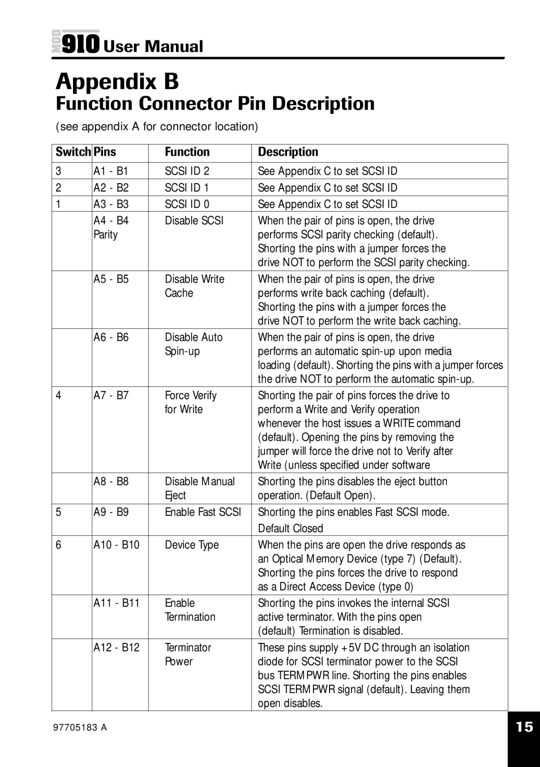
Appendix B
Function Connector Pin Description
(see appendix A for connector location)
Switch | Pins | Function | Description |
|
3 | A1 - B1 | SCSI ID 2 | See Appendix C to set SCSI ID |
|
2 | A2 - B2 | SCSI ID 1 | See Appendix C to set SCSI ID |
|
1 | A3 - B3 | SCSI ID 0 | See Appendix C to set SCSI ID |
|
| A4 - B4 | Disable SCSI | When the pair of pins is open, the drive | |
| Parity |
| performs SCSI parity checking (default). | |
|
|
| Shorting the pins with a jumper forces the | |
|
|
| drive NOT to perform the SCSI parity checking. |
|
| A5 - B5 | Disable Write | When the pair of pins is open, the drive | |
|
| Cache | performs write back caching (default). | |
|
|
| Shorting the pins with a jumper forces the | |
|
|
| drive NOT to perform the write back caching. |
|
| A6 - B6 | Disable Auto | When the pair of pins is open, the drive | |
|
| performs an automatic | ||
|
|
| loading (default). Shorting the pins with a jumper forces | |
|
|
| the drive NOT to perform the automatic |
|
4 | A7 - B7 | Force Verify | Shorting the pair of pins forces the drive to | |
|
| for Write | perform a Write and Verify operation | |
|
|
| whenever the host issues a WRITE command | |
|
|
| (default). Opening the pins by removing the | |
|
|
| jumper will force the drive not to Verify after | |
|
|
| Write (unless specified under software |
|
| A8 - B8 | Disable Manual | Shorting the pins disables the eject button | |
|
| Eject | operation. (Default Open). | |
5 | A9 - B9 | Enable Fast SCSI | Shorting the pins enables Fast SCSI mode. |
|
|
|
| Default Closed |
|
6 | A10 - B10 | Device Type | When the pins are open the drive responds as | |
|
|
| an Optical Memory Device (type 7) (Default). | |
|
|
| Shorting the pins forces the drive to respond | |
|
|
| as a Direct Access Device (type 0) |
|
| A11 - B11 | Enable | Shorting the pins invokes the internal SCSI | |
|
| Termination | active terminator. With the pins open | |
|
|
| (default) Termination is disabled. |
|
| A12 - B12 | Terminator | These pins supply +5V DC through an isolation | |
|
| Power | diode for SCSI terminator power to the SCSI | |
|
|
| bus TERMPWR line. Shorting the pins enables | |
|
|
| SCSI TERMPWR signal (default). Leaving them | |
|
|
| open disables. | |
97705183 A | 15 |
|
|