k- If the operator has removed pressure from exposure button all power will be removed and the shutter blades will open to permit viewing. If the button has not been released, the shutter blades will remain closed until the operator removes his finger from the button.
l- When a flash bar is placed in its socket, it closes switch S2. This switch connects the ECM in the flash mode. All of the mechanical sequences will remain as just described. The ECM however, will now provide power to solenoid #2 when switch S5 (in the gear train) opens, and will maintain it in a power down condition when S3 opens.
m- Within the shutter assembly a cam follower is driven by a cam on the focus wheel and arranged so that it will mechanically stop the travel of the shutter blades relative to the focus distance. When solenoid #2 is not energized, a spring on the cam follower prevents engagement of the cam follower and the shutter mechanism functions in the ambient exposure mode. When the ECM is programmed for flash, solenoid #2 is energized and the shutter openeing is controlled by focusing distance.
n- When making a flash exposure and the shutter blades start to open, the interceptor will be set to a position determined by the focusing mechanism but out of the path of the interceptor pin. When solenoid #2 is energized, it pulls the interceptor into the pins path of the blades and stops them
at the aperture for flash exposure at the set distance (Figure
o- The shutter performs an additional function in the flash mode. One of its circuits examines the #1 flashbulb contacts and by virtue of the resistance determines whethever or not the bulb has been fired. If the #1 lamp is exhausted, the circuit scans the #2, etc. When an unused lamp is located, the firing circuit remains connected to the lamp until is used.
NOTE : It is important to be aware that in early cameras the timing (integration) circuits of the substrate continue to function even though the insertion of a flash array has placed the substrate in the flash mode. Thus, if the ambient light level is high, the picture may be made by ambient light without firing the flash. Also, if all the flash lamps are expended and a picture is taken, an ambient light exposure will result. The photographer will recognize this situtation by the absence of a flash. However, he may still get an acceptable picture. the aperture in this case will be determined by the flash to subject distance.
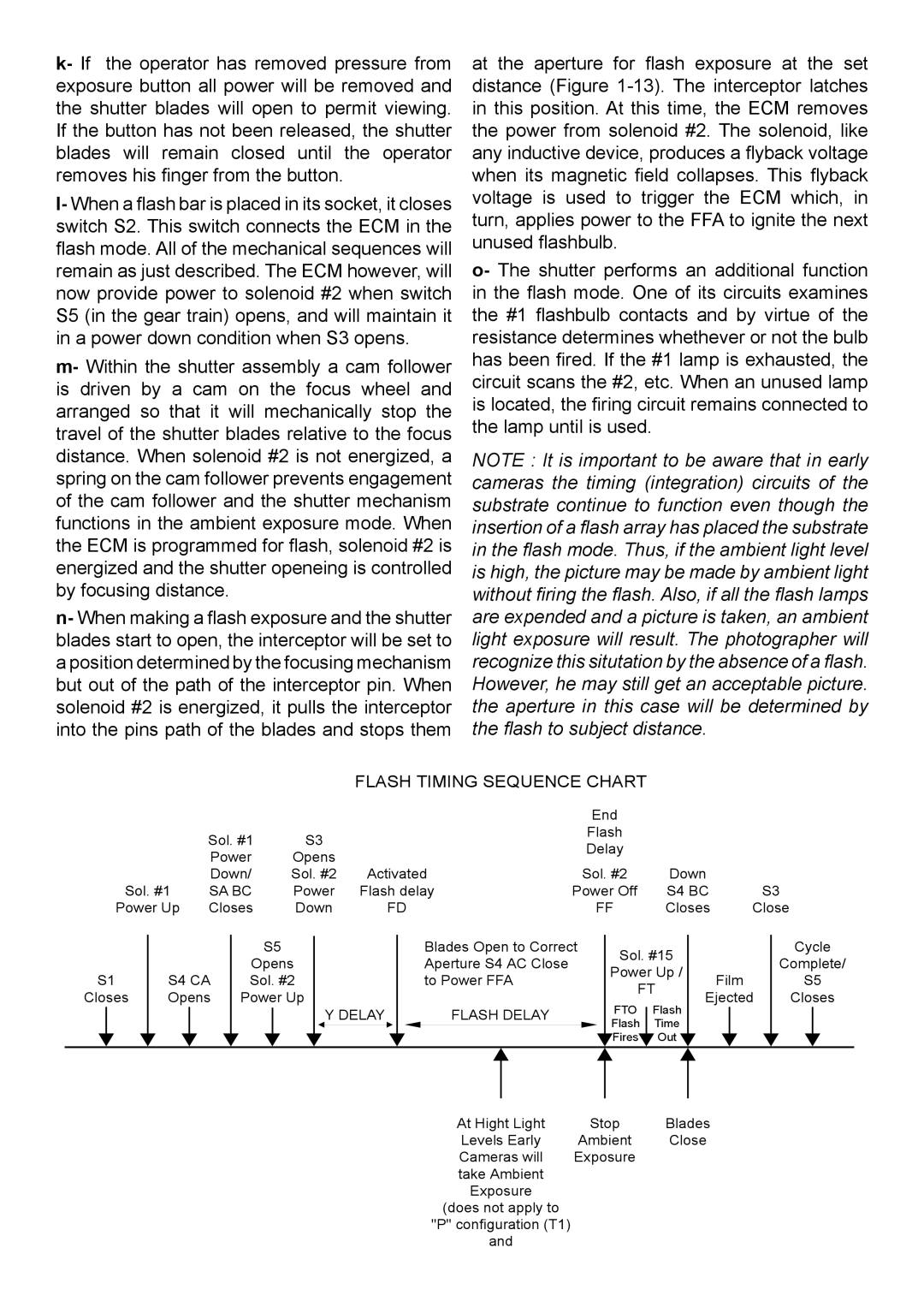
FLASH TIMING SEQUENCE CHART
|
|
|
| End |
|
|
| Sol. #1 | S3 |
| Flash |
|
|
|
| Delay |
|
| ||
| Power | Opens |
|
|
| |
|
|
|
|
| ||
| Down/ | Sol. #2 | Activated | Sol. #2 | Down |
|
Sol. #1 | SA BC | Power | Flash delay | Power Off | S4 BC | S3 |
Power Up | Closes | Down | FD | FF | Closes | Close |
S1
Closes
S4 CA Opens
S5
Opens
Sol. #2
Power Up
Y DELAY
Blades Open to Correct Aperture S4 AC Close to Power FFA
FLASH DELAY
Sol. #15 |
| |
Power Up / | Film | |
FT | ||
Ejected | ||
|
FTO Flash
Flash Time
![]() Fires
Fires![]() Out
Out ![]()
Cycle
Complete/
S5
Closes
At Hight Light | Stop | Blades |
Levels Early | Ambient | Close |
Cameras will | Exposure |
|
take Ambient |
|
|
Exposure |
|
|
(does not apply to |
|
|
"P" configuration (T1) |
|
|
and |
|
|