PA D2000.2 Power Inputs/Speaker Outputs
1 | 2 | 3 | 4 | 5 |
BRIDGED
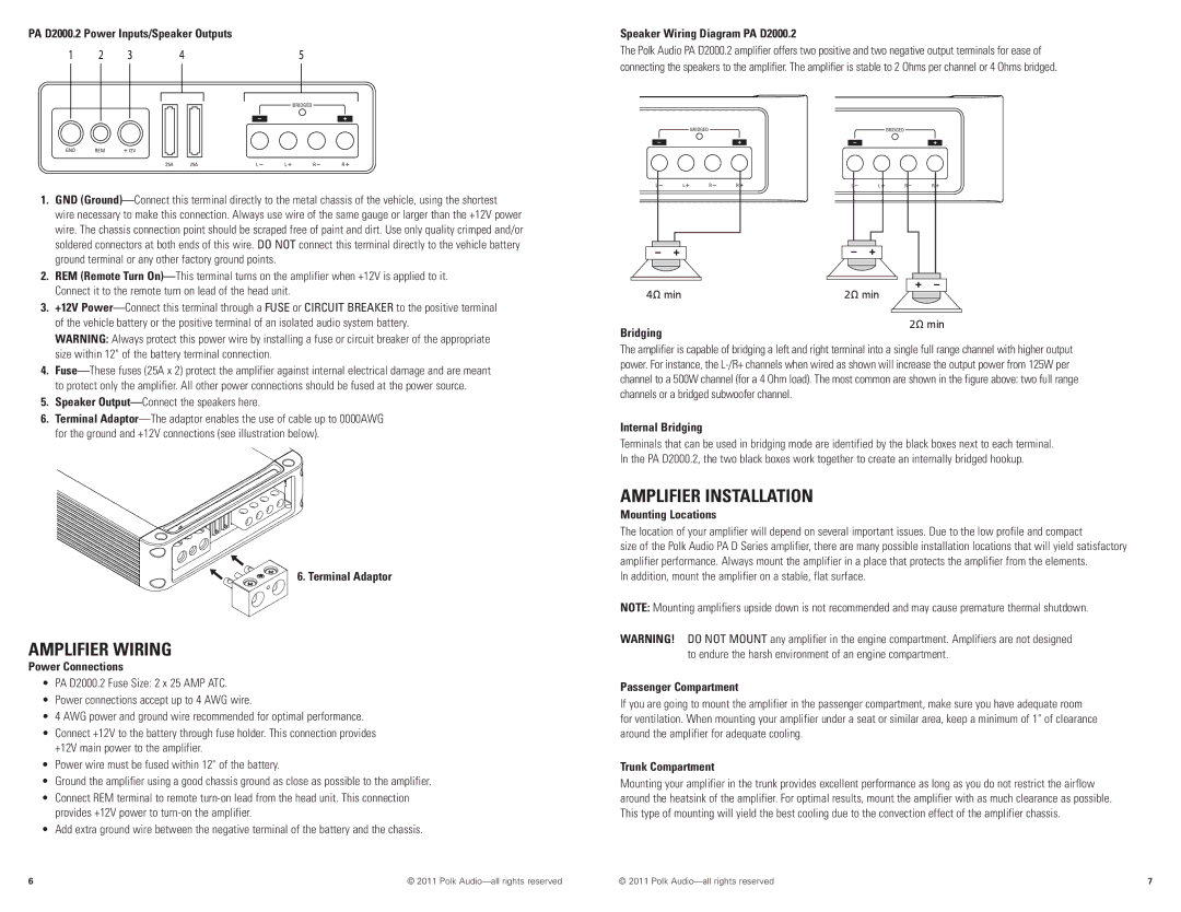
Speaker Wiring Diagram PA D2000.2
The Polk Audio PA D2000..2 amplifier offers two positive and two negative output terminals for ease of connecting the speakers to the amplifier.. The amplifier is stable to 2 Ohms per channel or 4 Ohms bridged..
GND REM ![]() 12V
12V
25A | 25A | L | L | R | R |
1. | GND |
| wire necessary to make this connection. Always use wire of the same gauge or larger than the +12V power |
| wire.. The chassis connection point should be scraped free of paint and dirt.. Use only quality crimped and/or |
| soldered connectors at both ends of this wire.. DO NOT connect this terminal directly to the vehicle battery |
| ground terminal or any other factory ground points.. |
2. | REM (Remote Turn |
BRIDGED
L | L | R | R |
BRIDGED
L | L | R | R |
Connect it to the remote turn on lead of the head unit.. |
3. +12V |
4Ω min | 2Ω min |
of the vehicle battery or the positive terminal of an isolated audio system battery.. |
WARNING: Always protect this power wire by installing a fuse or circuit breaker of the appropriate |
Bridging
2Ω min
| size within 12" of the battery terminal connection. |
4. | |
| to protect only the amplifier.. All other power connections should be fused at the power source.. |
5. | Speaker |
6. | Terminal |
| for the ground and +12V connections (see illustration below). |
6. Terminal Adaptor
Amplifier Wiring
Power Connections
•PA D2000.2 Fuse Size: 2 x 25 AMP ATC.
•Power connections accept up to 4 AWG wire.
•4 AWG power and ground wire recommended for optimal performance.
•Connect +12V to the battery through fuse holder. This connection provides +12V main power to the amplifier.
•Power wire must be fused within 12" of the battery.
•Ground the amplifier using a good chassis ground as close as possible to the amplifier.
•Connect REM terminal to remote
•Add extra ground wire between the negative terminal of the battery and the chassis.
The amplifier is capable of bridging a left and right terminal into a single full range channel with higher output power.. For instance, the
Internal Bridging
Terminals that can be used in bridging mode are identified by the black boxes next to each terminal.. In the PA D2000..2, the two black boxes work together to create an internally bridged hookup..
Amplifier Installation
Mounting Locations
The location of your amplifier will depend on several important issues.. Due to the low profile and compact
size of the Polk Audio PA D Series amplifier, there are many possible installation locations that will yield satisfactory amplifier performance.. Always mount the amplifier in a place that protects the amplifier from the elements..
In addition, mount the amplifier on a stable, flat surface..
NOTE: Mounting amplifiers upside down is not recommended and may cause premature thermal shutdown..
WARNING! Do not mount any amplifier in the engine compartment.. Amplifiers are not designed to endure the harsh environment of an engine compartment..
Passenger Compartment
If you are going to mount the amplifier in the passenger compartment, make sure you have adequate room for ventilation. When mounting your amplifier under a seat or similar area, keep a minimum of 1" of clearance around the amplifier for adequate cooling..
Trunk Compartment
Mounting your amplifier in the trunk provides excellent performance as long as you do not restrict the airflow around the heatsink of the amplifier.. For optimal results, mount the amplifier with as much clearance as possible.. This type of mounting will yield the best cooling due to the convection effect of the amplifier chassis..
6 | © 2011 Polk | © 2011 Polk | 7 |