LinkPlus Interface Guide: Siemens Hicom/HiPath optiset for SpectraLink e340/h340/i640 Wireless Telephones
LED emulation
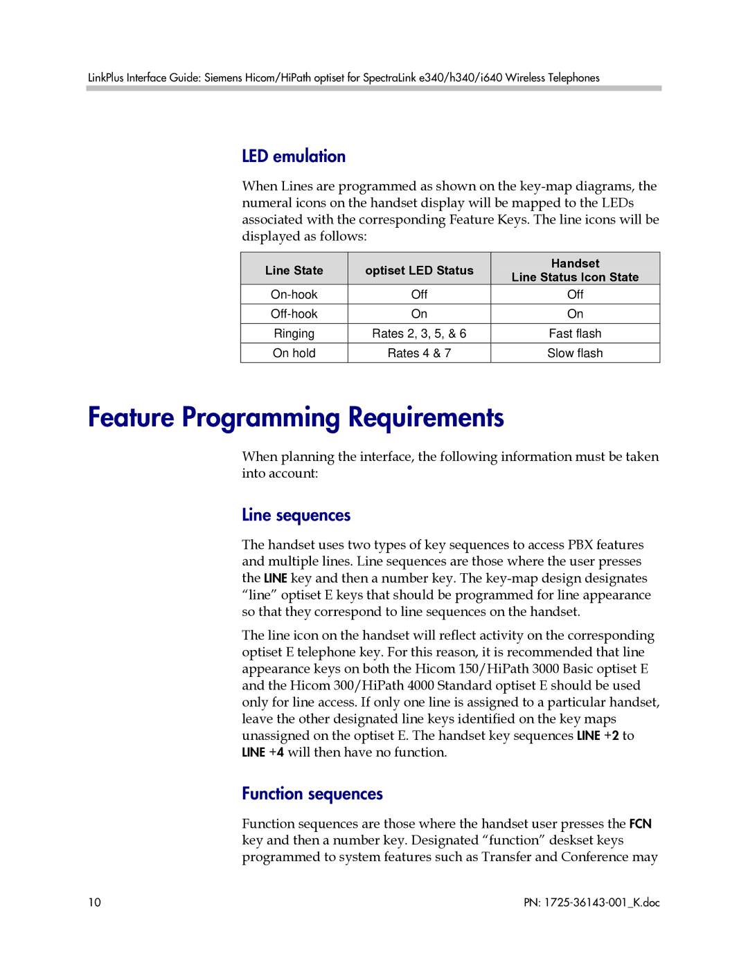
When Lines are programmed as shown on the
| Line State |
|
| optiset LED Status |
| Handset |
|
|
|
| Line Status Icon State | ||
|
|
|
|
|
| |
|
| Off | Off | |||
|
|
|
|
| ||
|
| On | On | |||
| Ringing |
| Rates 2, 3, 5, & 6 | Fast flash | ||
| On hold |
| Rates 4 & 7 | Slow flash | ||
|
|
|
|
|
|
|
Feature Programming Requirements
When planning the interface, the following information must be taken into account:
Line sequences
The handset uses two types of key sequences to access PBX features and multiple lines. Line sequences are those where the user presses the LINE key and then a number key. The
The line icon on the handset will reflect activity on the corresponding optiset E telephone key. For this reason, it is recommended that line appearance keys on both the Hicom 150/HiPath 3000 Basic optiset E and the Hicom 300/HiPath 4000 Standard optiset E should be used only for line access. If only one line is assigned to a particular handset, leave the other designated line keys identified on the key maps unassigned on the optiset E. The handset key sequences LINE +2 to LINE +4 will then have no function.
Function sequences
Function sequences are those where the handset user presses the FCN key and then a number key. Designated “function” deskset keys programmed to system features such as Transfer and Conference may
10 | PN: |
