ADJUSTING OVERARM COLUMN
If side motion develops in the overarm, after extended use, it can be corrected as follows:
1. DISCONNECT MACHINE FROM
POWER SOURCE.
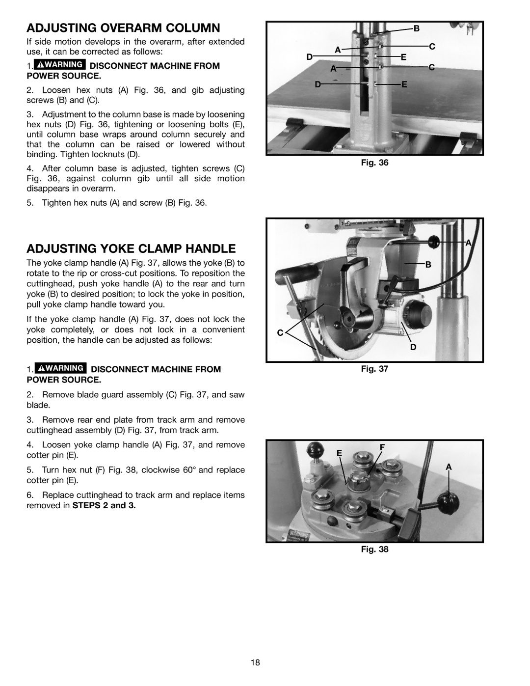
2.Loosen hex nuts (A) Fig. 36, and gib adjusting screws (B) and (C).
3.Adjustment to the column base is made by loosening hex nuts (D) Fig. 36, tightening or loosening bolts (E), until column base wraps around column securely and that the column can be raised or lowered without binding. Tighten locknuts (D).
4.After column base is adjusted, tighten screws (C) Fig. 36, against column gib until all side motion disappears in overarm.
5.Tighten hex nuts (A) and screw (B) Fig. 36.
B
A![]()
![]() C
C
DE
AC
DE
Fig. 36
ADJUSTING YOKE CLAMP HANDLE
The yoke clamp handle (A) Fig. 37, allows the yoke (B) to rotate to the rip or
If the yoke clamp handle (A) Fig. 37, does not lock the yoke completely, or does not lock in a convenient position, the handle can be adjusted as follows:
1. DISCONNECT MACHINE FROM
POWER SOURCE.
A
B
C
D
Fig. 37
2.Remove blade guard assembly (C) Fig. 37, and saw blade.
3.Remove rear end plate from track arm and remove cuttinghead assembly (D) Fig. 37, from track arm.
4.Loosen yoke clamp handle (A) Fig. 37, and remove cotter pin (E).
5.Turn hex nut (F) Fig. 38, clockwise 60° and replace cotter pin (E).
6.Replace cuttinghead to track arm and replace items removed in STEPS 2 and 3.
E
F
A
Fig. 38
18