PORTER-CABLE / ROCKWELL PROFESSIONAL ROUTERS
Router Model | Max. Bit Diameter |
All Models rated less than 2 Horsepower | 21… 8" |
All Models rated over 2 Horsepower | 31… 2" |
|
|
INSTALLING AND REMOVING BIT
1.CAUTION: DISCONNECT MACHINE FROM POWER SOURCE.
2.Clean and insert shank of bit into collect until shank bottoms. Then back it out approximately 1… 16".
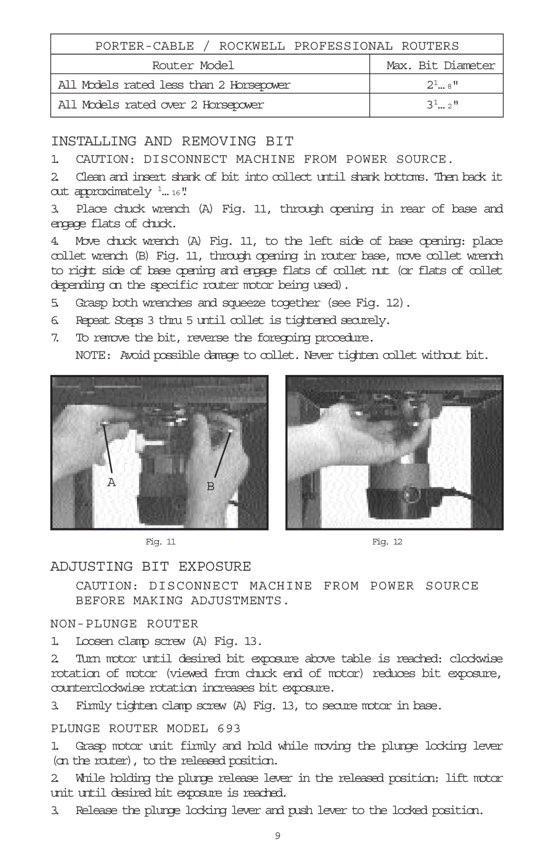
3.Place chuck wrench (A) Fig. 11, through opening in rear of base and engage flats of chuck.
4.Move chuck wrench (A) Fig. 11, to the left side of base opening: place collet wrench (B) Fig. 11, through opening in router base, move collet wrench to right side of base opening and engage flats of collet nut (or flats of collet depending on the specific router motor being used).
5.Grasp both wrenches and squeeze together (see Fig. 12).
6.Repeat Steps 3 thru 5 until collet is tightened securely.
7.To remove the bit, reverse the foregoing procedure.
NOTE: Avoid possible damage to collet. Never tighten collet without bit.
AB
Fig. 11 | Fig. 12 |
ADJUSTING BIT EXPOSURE
CAUTION: DISCONNECT MACHINE FROM POWER SOURCE BEFORE MAKING ADJUSTMENTS.
NON-PLUNGE ROUTER
1.Loosen clamp screw (A) Fig. 13.
2.Turn motor until desired bit exposure above table is reached: clockwise rotation of motor (viewed from chuck end of motor) reduces bit exposure, counterclockwise rotation increases bit exposure.
3.Firmly tighten clamp screw (A) Fig. 13, to secure motor in base.
PLUNGE ROUTER MODEL 693
1.Grasp motor unit firmly and hold while moving the plunge locking lever (on the router), to the released position.
2.While holding the plunge release lever in the released position: lift motor unit until desired bit exposure is reached.
3.Release the plunge locking lever and push lever to the locked position.
9