![]()
![]()
![]()
![]()
![]()
![]()
![]()
![]()
![]() TM
TM
APPLICATION
KEYBOARD CONSTRUCTION
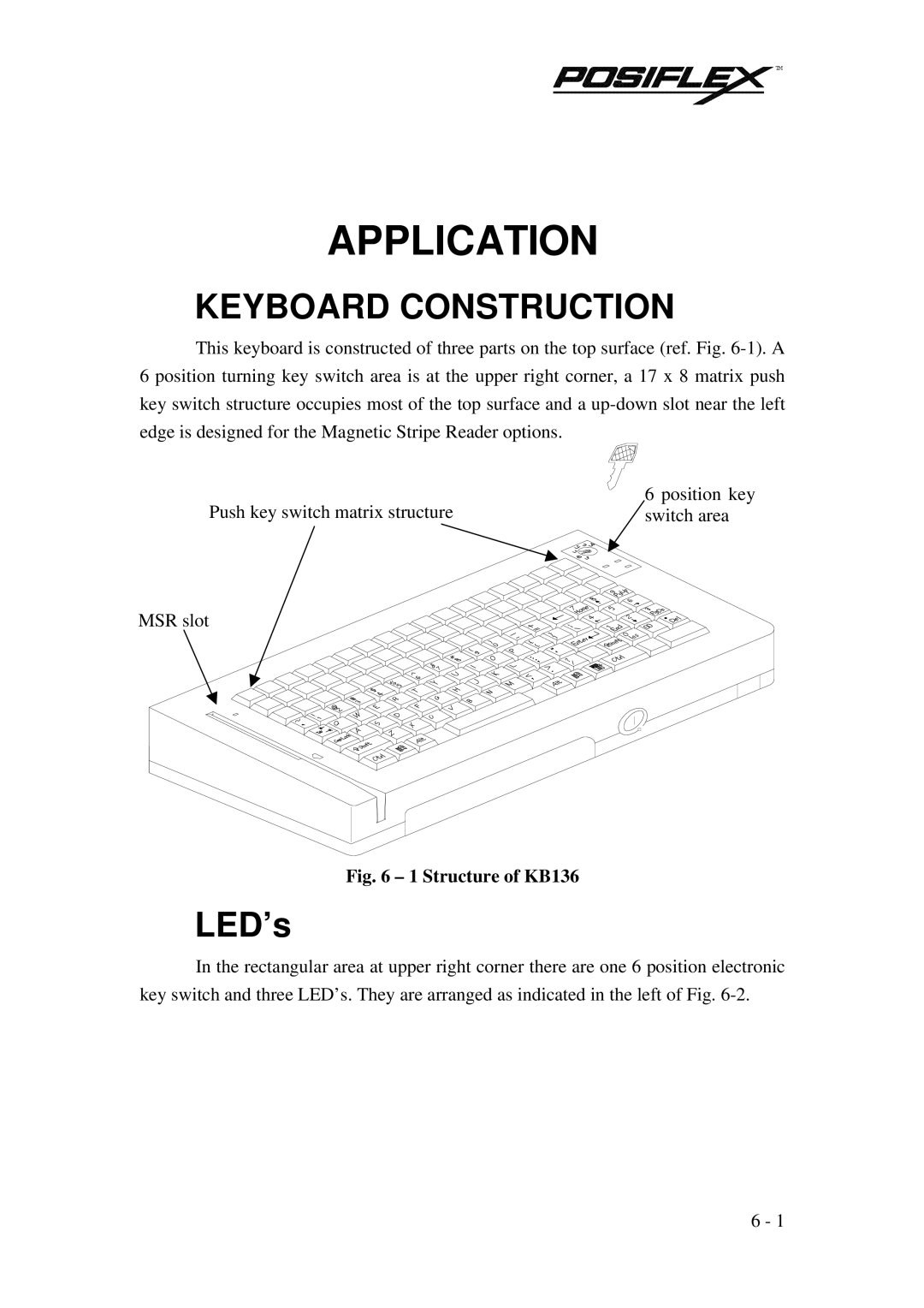
This keyboard is constructed of three parts on the top surface (ref. Fig.
Push key switch matrix structure | 6 position key |
switch area |
MSR slot
Fig. 6 – 1 Structure of KB136
LED’s
In the rectangular area at upper right corner there are one 6 position electronic key switch and three LED’s. They are arranged as indicated in the left of Fig.
6 - 1
