![]()
![]()
![]()
![]()
![]()
![]()
![]()
![]()
![]() TM
TM
L2 L3
L1L4
LP
Caps Lock
L2 | L3 |
L1 | L4 |
LP |
|
POWER | |
Num.Lock | Caps Lock |
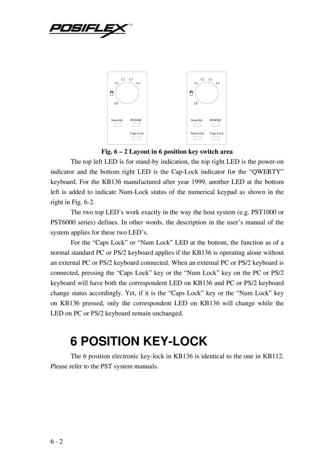
Fig. 6 – 2 Layout in 6 position key switch area
The top left LED is for
The two top LED’s work exactly in the way the host system (e.g. PST1000 or PST6000 series) defines. In other words, the description in the user’s manual of the system applies for these two LED’s.
For the “Caps Lock” or “Num Lock” LED at the bottom, the function as of a normal standard PC or PS/2 keyboard applies if the KB136 is operating alone without an external PC or PS/2 keyboard connected. When an external PC or PS/2 keyboard is connected, pressing the “Caps Lock” key or the “Num Lock” key on the PC or PS/2 keyboard will have both the correspondent LED on KB136 and PC or PS/2 keyboard change status accordingly. Yet, if it is the “Caps Lock” key or the “Num Lock” key on KB136 pressed, only the correspondent LED on KB136 will change while the LED on PC or PS/2 keyboard remain unchanged.
6 POSITION KEY-LOCK
The 6 position electronic
6 - 2