4.Pull starter rope handle sharply until en- gine starts and runs.

5.Allow unit to run for 10--15 seconds, then fully squeeze the throttle trigger to disen- gage the starting system.

STARTING A WARM ENGINE

1.Squeeze and hold the throttle trigger. Keep throttle trigger fully squeezed until engine runs smoothly.

2.Pull starter rope sharply while squeezing throttle trigger until engine runs.

NOTE: Normally, the warm starting procedure can be used within 5--10 minutes after the unit is turned off. If the unit sits for more than 10 min- utes without being ran, it will be necessary to start the unit by following the steps under STARTING A COLD ENGINE or following the starting instruction steps shown on the unit.

STARTING A FLOODED ENGINE

Flooded engines can be started by placing the start lever to the RUN position. Fully squeeze throttle trigger. Pull the starter han- dle repeatedly while squeezing throttle trigger until engine starts and runs. This could re- quire pulling the starter handle many times, depending on how badly the unit is flooded. If the unit still doesn’t start, refer to TROUBLESHOOTING TABLE or call 1-800-554-6723.

OPERATING THE COUPLER

This model is equipped with a coupler which enables optional attachments to be installed. The optional attachments are:

MODEL: Cultivator . . . . . . . . . . . . . . . . . . . PP2000T Blower . . . . . . . . . . . . . . . . . . . . . PP3000B Brushcutter . . . . . . . . . . . . . . . . . PP4000C Pruner . . . . . . . . . . . . . . . . . . . . . PP5000P Pruner . . . . . . . . . . . . . . . . . . . . . PP5500P

WARNING: Always stop unit and dis- connect spark plug before removing or instal- ling attachments.

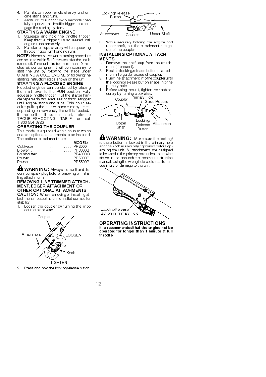
REMOVING LINE TRIMMER ATTACH- MENT, EDGER ATTACHMENT OR OTHER OPTIONAL ATTACHMENTS CAUTION: When removing or installing at-

tachments, place the unit on a flat surface for stability.

1.Loosen the coupler by turning the knob counterclockwise.

Coupler

AttachmentLOOSEN

Knob

TIGHTEN

2. Press and hold the locking/release button.

Locking/Release

Button

Attachment

Coupler

Upper Shaft

3.While securely holding the engine and upper shaft, pull the attachment straight out of the coupler.

INSTALLING OPTIONAL ATTACH- MENTS

1.Remove the shaft cap from the attach- ment (if present).

2.Position locking/release button of attach- ment into guide recess of coupler.

3.Push the attachment into the coupler until the locking/release button snaps into the primary hole.

4.Before using the unit, tighten the knob se- curely by turning clockwise.

Coupler Primary Hole

Guide Recess

Locking/

Upper Release Attachment

Shaft Button

WARNING: Make sure the locking/ release button is locked in the primary hole and the knob is securely tightened before op- erating the unit. All attachments are designed to be used in the primary hole unless otherwise stated in the applicable attachment instruction manual. Using the wrong hole could lead to seri- ous injury or damage to the unit.

Locking/Release

Button in Primary Hole

OPERATING INSTRUCTIONS

It is recommended that the engine not be operated for longer than 1 minute at full throttle.

12

Page 12
Image 12
Poulan 952711963 Operating Instructions, Starting a Warm Engine, Starting a Flooded Engine, Operating the Coupler

115275026, 952711963 specifications

The Poulan 115275026 and 952711963 are two high-quality replacement parts designed for Poulan chainsaws, known for their reliability and efficient functionality. These components play a crucial role in maintaining the performance of your chainsaw, ensuring that it operates smoothly and effectively during your cutting tasks.

One of the standout features of these replacement parts is their exceptional durability. Made from high-grade materials, they are built to withstand the rigors of heavy use. This durability not only extends the overall lifespan of the chainsaw but also enhances its performance by ensuring consistent power delivery and efficiency. Users can expect these parts to perform well even under challenging conditions, making them ideal for both professional and DIY applications.

In terms of technology, the Poulan 115275026 and 952711963 boast advanced engineering design that helps improve the chainsaw's fuel efficiency. This innovative approach minimizes fuel consumption while maximizing cutting performance, ultimately saving users money on both fuel and maintenance costs in the long run. Additionally, these parts are designed to minimize vibration, providing a smoother operation experience. This not only enhances user comfort but also improves precision during cutting tasks.

Another remarkable characteristic of these replacement parts is their easy installation. Poulan has designed these components to fit seamlessly into a variety of chainsaw models, allowing for quick and hassle-free replacement. This user-friendly design means that even those with limited mechanical skills can easily replace worn-out parts, ensuring their chainsaw is always in top condition.

Furthermore, the Poulan 115275026 and 952711963 are backed by a reputable brand known for its commitment to quality and customer satisfaction. This ensures that users receive a product they can trust, complete with the necessary support and guidance if needed.

In summary, the Poulan 115275026 and 952711963 replacement parts embody the quality and innovation that Poulan is known for in the chainsaw industry. Their durability, advanced technology, ease of installation, and strong brand reputation make them an excellent choice for anyone looking to maintain or upgrade their Poulan chainsaw. Investing in these replacement parts ensures optimal performance and longevity, making them a wise choice for all chainsaw users.