8.3Stand assembly
Assembly tip: A ratchet wrench with sockets and extensions will speed assembly time.
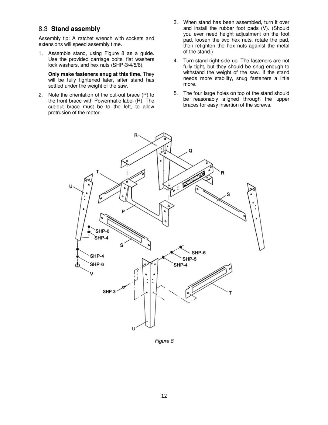
1.Assemble stand, using Figure 8 as a guide. Use the provided carriage bolts, flat washers lock washers, and hex nuts
Only make fasteners snug at this time. They will be fully tightened later, after stand has settled under the weight of the saw.
2.Note the orientation of the
3.When stand has been assembled, turn it over and install the rubber foot pads (V). (Should you ever need height adjustment on the foot pad, loosen the two hex nuts, rotate the pad, then retighten the hex nuts against the metal of the stand.)
4.Turn stand
5.The four large holes on top of the stand should be reasonably aligned through the upper braces for easy insertion of the screws.
Figure 8
12