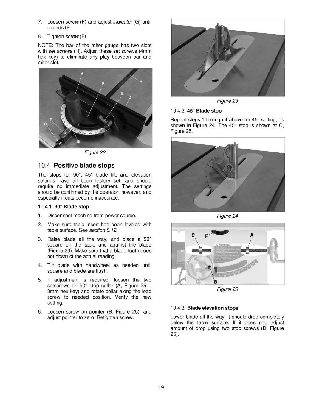
7.Loosen screw (F) and adjust indicator (G) until it reads 0º.
8.Tighten screw (F).
NOTE: The bar of the miter gauge has two slots with set screws (H). Adjust these set screws (4mm hex key) to eliminate any play between bar and miter slot.
Figure 22
10.4Positive blade stops
The stops for 90°, 45° blade tilt, and elevation settings have all been factory set, and should require no immediate adjustment. The settings should be confirmed by the operator, however, and especially if cuts become inaccurate.
10.4.190° Blade stop
1.Disconnect machine from power source.
2.Make sure table insert has been leveled with table surface. See section 8.12.
3.Raise blade all the way, and place a 90° square on the table and against the blade (Figure 23). Make sure that a blade tooth does not obstruct the actual reading.
4.Tilt blade with handwheel as needed until square and blade are flush.
5.If adjustment is required, loosen the two setscrews on 90° stop collar (A, Figure 25 – 3mm hex key) and rotate collar along the lead screw to needed position. Verify the new setting.
6.Loosen screw on pointer (B, Figure 25), and adjust pointer to zero. Retighten screw.
Figure 23
10.4.245° Blade stop
Repeat steps 1 through 4 above for 45° setting, as shown in Figure 24. The 45° stop is shown at C, Figure 25.
Figure 24
Figure 25
10.4.3Blade elevation stops
Lower blade all the way; it should drop completely below the table surface. If it does not, adjust amount of drop using two stop screws (D, Figure 26).
19