Figure 29
Figure 30
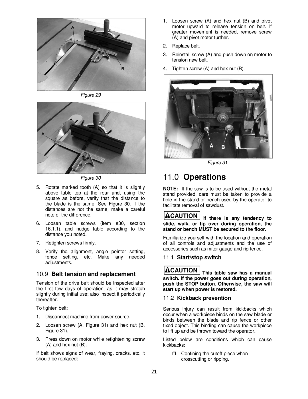
5.Rotate marked tooth (A) so that it is slightly above table top at the rear and, using the square as before, verify that the distance to the blade is the same. See Figure 30. If the distances are not the same, make a careful note of the difference.
6.Loosen table screws (item #30, section 16.1.1), and nudge table according to the distance you noted.
7.Retighten screws firmly.
8.Verify the alignment, angle pointer setting, fence setting, etc. Make any needed adjustments.
10.9Belt tension and replacement
Tension of the drive belt should be inspected after the first few days of operation, as it may stretch slightly during initial use; also inspect it periodically thereafter.
To tighten belt:
1.Disconnect machine from power source.
2.Loosen screw (A, Figure 31) and hex nut (B, Figure 31).
3.Press down on motor while retightening screw
(A) and hex nut (B).
If belt shows signs of wear, fraying, cracks, etc. it should be replaced:
1.Loosen screw (A) and hex nut (B) and pivot motor upward to release tension on belt. If greater movement is needed, remove screw
(A) and pivot motor further.
2.Replace belt.
3.Reinstall screw (A) and push down on motor to tension new belt.
4.Tighten screw (A) and hex nut (B).
Figure 31
11.0Operations
NOTE: If the saw is to be used without the metal stand provided, care must be taken to provide a hole in the stand or bench used by the operator to facilitate removal of sawdust.
![]() If there is any tendency to slide, walk, or tip over during operation, the stand or bench MUST be secured to the floor.
If there is any tendency to slide, walk, or tip over during operation, the stand or bench MUST be secured to the floor.
Familiarize yourself with the location and operation of all controls and adjustments and the use of accessories such as miter gauge and rip fence.
11.1Start/stop switch
![]() This table saw has a manual switch. If the power goes out during operation, push the STOP button. Otherwise, the saw will start up when power is restored.
This table saw has a manual switch. If the power goes out during operation, push the STOP button. Otherwise, the saw will start up when power is restored.
11.2Kickback prevention
Serious injury can result from kickbacks which occur when a workpiece binds on the saw blade or binds between the blade and rip fence or other fixed object. This binding can cause the workpiece to lift up and be thrown toward the operator.
Listed below are conditions which can cause kickbacks:
Confining the cutoff piece when crosscutting or ripping.
21
