230 Volt Operation
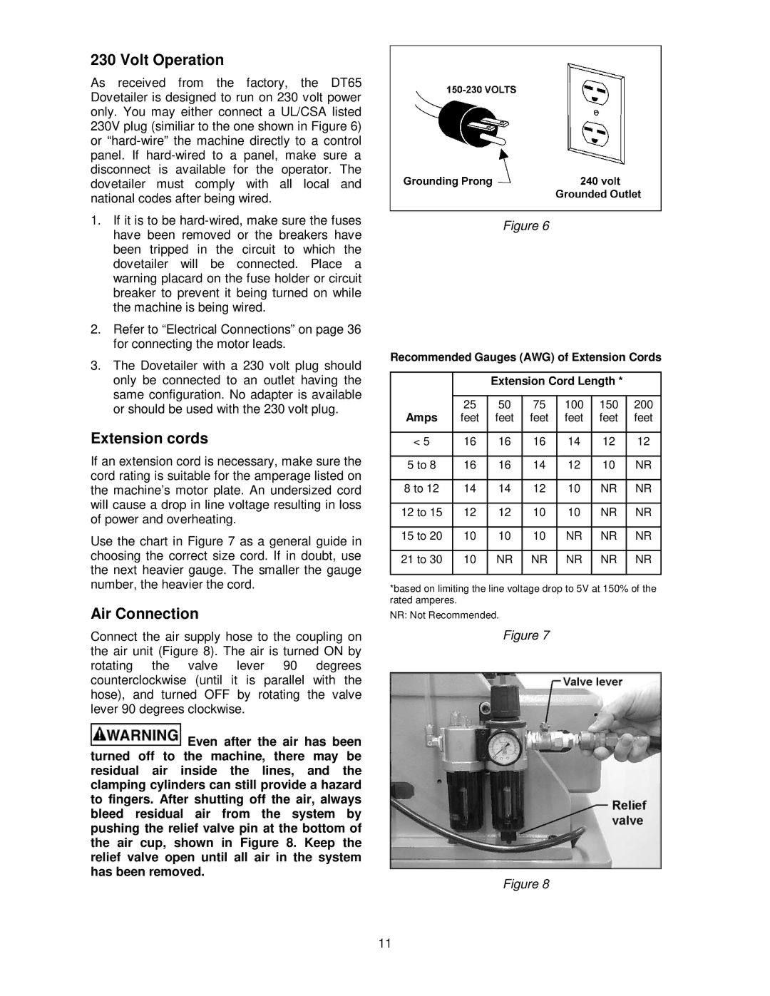
As received from the factory, the DT65 Dovetailer is designed to run on 230 volt power only. You may either connect a UL/CSA listed 230V plug (similiar to the one shown in Figure 6) or
1.If it is to be
2.Refer to “Electrical Connections” on page 36 for connecting the motor leads.
3.The Dovetailer with a 230 volt plug should only be connected to an outlet having the same configuration. No adapter is available or should be used with the 230 volt plug.
Extension cords
If an extension cord is necessary, make sure the cord rating is suitable for the amperage listed on the machine’s motor plate. An undersized cord will cause a drop in line voltage resulting in loss of power and overheating.
Use the chart in Figure 7 as a general guide in choosing the correct size cord. If in doubt, use the next heavier gauge. The smaller the gauge number, the heavier the cord.
Air Connection
Connect the air supply hose to the coupling on the air unit (Figure 8). The air is turned ON by rotating the valve lever 90 degrees counterclockwise (until it is parallel with the hose), and turned OFF by rotating the valve lever 90 degrees clockwise.
![]() Even after the air has been turned off to the machine, there may be residual air inside the lines, and the clamping cylinders can still provide a hazard to fingers. After shutting off the air, always bleed residual air from the system by pushing the relief valve pin at the bottom of the air cup, shown in Figure 8. Keep the relief valve open until all air in the system has been removed.
Even after the air has been turned off to the machine, there may be residual air inside the lines, and the clamping cylinders can still provide a hazard to fingers. After shutting off the air, always bleed residual air from the system by pushing the relief valve pin at the bottom of the air cup, shown in Figure 8. Keep the relief valve open until all air in the system has been removed.
Figure 6
Recommended Gauges (AWG) of Extension Cords
|
|
| Extension Cord Length * |
| |||
|
|
|
|
|
|
|
|
Amps | 25 | 50 | 75 | 100 | 150 | 200 | |
feet | feet | feet | feet | feet | feet | ||
|
|
|
|
|
|
|
|
< 5 |
| 16 | 16 | 16 | 14 | 12 | 12 |
|
|
|
|
|
|
|
|
5 to | 8 | 16 | 16 | 14 | 12 | 10 | NR |
|
|
|
|
|
|
| |
8 to 12 | 14 | 14 | 12 | 10 | NR | NR | |
|
|
|
|
|
|
|
|
12 to | 15 | 12 | 12 | 10 | 10 | NR | NR |
|
|
|
|
|
|
|
|
15 to | 20 | 10 | 10 | 10 | NR | NR | NR |
|
|
|
|
|
|
|
|
21 to | 30 | 10 | NR | NR | NR | NR | NR |
|
|
|
|
|
|
|
|
*based on limiting the line voltage drop to 5V at 150% of the rated amperes.
NR: Not Recommended.
Figure 7
Figure 8
11