Adjustments
![]() Disconnect machine from power source, shut off air supply and bleed residual air from system, before making adjustments. Failure to comply may cause serious injury.
Disconnect machine from power source, shut off air supply and bleed residual air from system, before making adjustments. Failure to comply may cause serious injury.
Clamping Cylinders
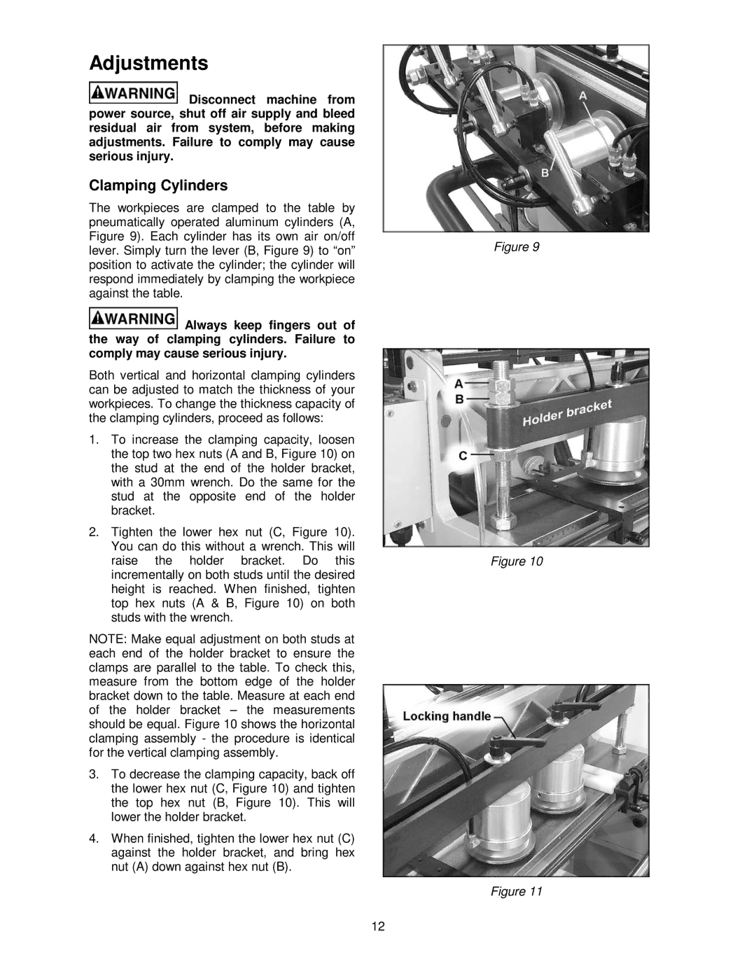
The workpieces are clamped to the table by pneumatically operated aluminum cylinders (A, Figure 9). Each cylinder has its own air on/off lever. Simply turn the lever (B, Figure 9) to “on” position to activate the cylinder; the cylinder will respond immediately by clamping the workpiece against the table.
![]() Always keep fingers out of the way of clamping cylinders. Failure to comply may cause serious injury.
Always keep fingers out of the way of clamping cylinders. Failure to comply may cause serious injury.
Both vertical and horizontal clamping cylinders can be adjusted to match the thickness of your workpieces. To change the thickness capacity of the clamping cylinders, proceed as follows:
1.To increase the clamping capacity, loosen the top two hex nuts (A and B, Figure 10) on the stud at the end of the holder bracket, with a 30mm wrench. Do the same for the stud at the opposite end of the holder bracket.
2.Tighten the lower hex nut (C, Figure 10). You can do this without a wrench. This will raise the holder bracket. Do this incrementally on both studs until the desired height is reached. When finished, tighten top hex nuts (A & B, Figure 10) on both studs with the wrench.
NOTE: Make equal adjustment on both studs at each end of the holder bracket to ensure the clamps are parallel to the table. To check this, measure from the bottom edge of the holder bracket down to the table. Measure at each end of the holder bracket – the measurements should be equal. Figure 10 shows the horizontal clamping assembly - the procedure is identical for the vertical clamping assembly.
3.To decrease the clamping capacity, back off the lower hex nut (C, Figure 10) and tighten the top hex nut (B, Figure 10). This will lower the holder bracket.
4.When finished, tighten the lower hex nut (C) against the holder bracket, and bring hex nut (A) down against hex nut (B).
Figure 9
Figure 10
Figure 11
12