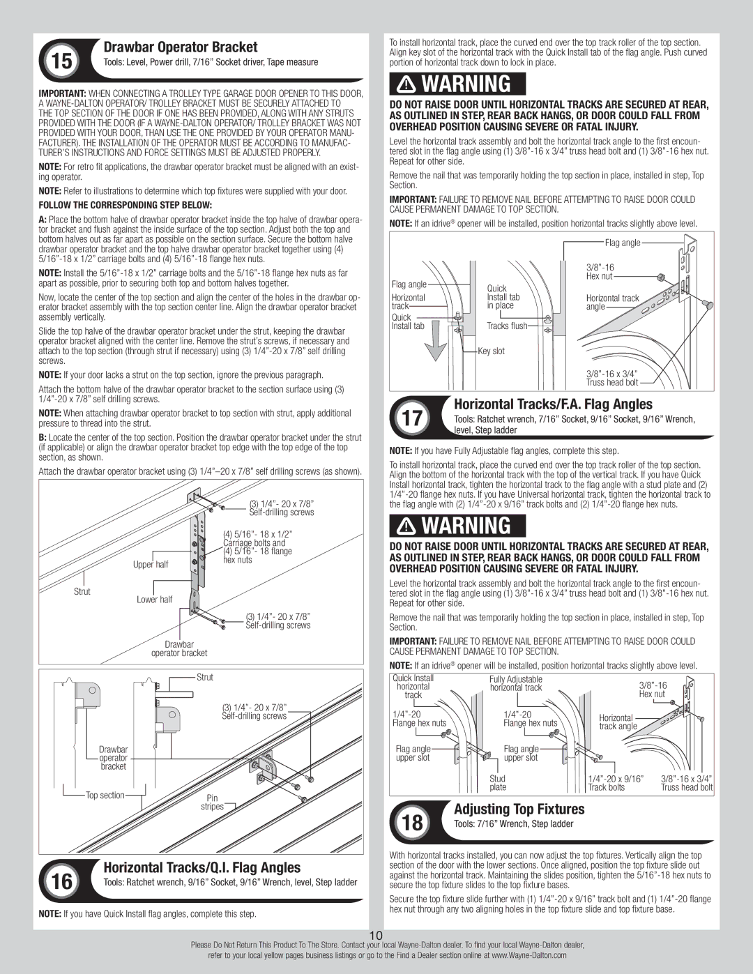
| 15 | Drawbar Operator Bracket |
| Tools: Level, Power drill, 7/16” Socket driver, Tape measure |
| |
Important: When connecting a trolley type garage door opener to this door, a Wayne-Dalton operator/ trolley bracket must be securely attached to
the top section of the door if one has been provided, along with any struts provided with the door (if a Wayne-Dalton operator/ trolley bracket was not provided with your door, than use the one provided by your operator manu- facturer). The installation of the operator must be according to manufac- turer’s instructions and force settings must be adjusted properly.
NOTE: For retro fit applications, the drawbar operator bracket must be aligned with an exist- ing operator.
NOTE: Refer to illustrations to determine which top fixtures were supplied with your door.
Follow the corresponding step below:
A:Place the bottom halve of drawbar operator bracket inside the top halve of drawbar opera- tor bracket and flush against the inside surface of the top section. Adjust both the top and bottom halves out as far apart as possible on the section surface. Secure the bottom halve drawbar operator bracket and the top halve drawbar operator bracket together using (4) 5/16”-18 x 1/2” carriage bolts and (4) 5/16”-18 flange hex nuts.
NOTE: Install the 5/16”-18 x 1/2” carriage bolts and the 5/16”-18 flange hex nuts as far apart as possible, prior to securing both top and bottom halves together.
Now, locate the center of the top section and align the center of the holes in the drawbar op- erator bracket assembly with the top section center line. Align the drawbar operator bracket assembly vertically.
Slide the top halve of the drawbar operator bracket under the strut, keeping the drawbar operator bracket aligned with the center line. Remove the strut’s screws, if necessary and attach to the top section (through strut if necessary) using (3) 1/4”-20 x 7/8” self drilling screws.
NOTE: If your door lacks a strut on the top section, ignore the previous paragraph.
Attach the bottom halve of the drawbar operator bracket to the section surface using (3) 1/4”-20 x 7/8” self drilling screws.
NOTE: When attaching drawbar operator bracket to top section with strut, apply additional pressure to thread into the strut.
B:Locate the center of the top section. Position the drawbar operator bracket under the strut (if applicable) or align the drawbar operator bracket top edge with the top edge of the top section, as shown.
Attach the drawbar operator bracket using (3) 1/4”–20 x 7/8” self drilling screws (as shown).
| (3) 1/4”- 20 x 7/8” |
| Self-drilling screws |
| (4) 5/16”- 18 x 1/2” |
| Carriage bolts and |
| (4) 5/16”- 18 flange |
Upper half | hex nuts |
|
Strut | |
Lower half | |
| (3) 1/4”- 20 x 7/8” |
| Self-drilling screws |
Drawbar | |
operator bracket | |
Strut | |
| (3) 1/4”- 20 x 7/8” |
| Self-drilling screws |
Drawbar | |
operator | |
bracket | |
Top section | Pin |
| stripes |
| 16 | Horizontal Tracks/Q.I. Flag Angles |
| Tools: Ratchet wrench, 9/16” Socket, 9/16” Wrench, level, Step ladder |
| |
Note: If you have Quick Install flag angles, complete this step.
To install horizontal track, place the curved end over the top track roller of the top section. Align key slot of the horizontal track with the Quick Install tab of the flag angle. Push curved portion of horizontal track down to lock in place.
 WARNING
Do not raise door until horizontal tracks are secured at rear, as outlined in Step, Rear Back Hangs, or door could fall from overhead position causing severe or fatal injury.
Level the horizontal track assembly and bolt the horizontal track angle to the first encoun- tered slot in the flag angle using (1) 3/8”-16 x 3/4” truss head bolt and (1) 3/8”-16 hex nut. Repeat for other side.
Remove the nail that was temporarily holding the top section in place, installed in step, Top Section.
Important: Failure to remove nail before attempting to raise door could cause permanent damage to top section.
Note: If an idrive® opener will be installed, position horizontal tracks slightly above level.
| | Flag angle |
| | 3/8”-16 |
Flag angle | | Hex nut |
Quick | |
| |
Horizontal | Install tab | Horizontal track |
track | in place | angle |
Quick | Tracks flush | |
Install tab | |
| Key slot | |
| | 3/8”-16 x 3/4” |
| | Truss head bolt |
| 17 | Horizontal Tracks/F.A. Flag Angles |
| Tools: Ratchet wrench, 7/16” Socket, 9/16” Socket, 9/16” Wrench, |
| |
| | level, Step ladder |
Note: If you have Fully Adjustable flag angles, complete this step.
To install horizontal track, place the curved end over the top track roller of the top section. Align the bottom of the horizontal track with the top of the vertical track. If you have Quick Install horizontal track, tighten the horizontal track to the flag angle with a stud plate and (2) 1/4”-20 flange hex nuts. If you have Universal horizontal track, tighten the horizontal track to the flag angle with (2) 1/4”-20 x 9/16” track bolts and (2) 1/4”-20 flange hex nuts.
 WARNING
Do not raise door until horizontal tracks are secured at rear, as outlined in step, Rear Back Hangs, or door could fall from overhead position causing severe or fatal injury.
Level the horizontal track assembly and bolt the horizontal track angle to the first encoun- tered slot in the flag angle using (1) 3/8”-16 x 3/4” truss head bolt and (1) 3/8”-16 hex nut. Repeat for other side.
Remove the nail that was temporarily holding the top section in place, installed in step, Top Section.
Important: Failure to remove nail before attempting to raise door could cause permanent damage to top section.
Note: If an idrive® opener will be installed, position horizontal tracks slightly above level.
| Quick Install | Fully Adjustable | 3/8”-16 |
| horizontal | horizontal track |
| track | | Hex nut |
| 1/4”-20 | 1/4”-20 | Horizontal |
| Flange hex nuts | Flange hex nuts |
| track angle |
| | |
| Flag angle | Flag angle | |
| upper slot | upper slot | |
Stud | | | | 3/8”-16 x 3/4” |
1/4”-20 x 9/16” |
plate | Track bolts | Truss head bolt |
| 18 | Adjusting Top Fixtures |
| Tools: 7/16” Wrench, Step ladder |
| |
With horizontal tracks installed, you can now adjust the top fixtures. Vertically align the top section of the door with the lower sections. Once aligned, position the top fixture slide out against the horizontal track. Maintaining the slides position, tighten the 5/16”-18 hex nuts to secure the top fixture slides to the top fixture bases.
Secure the top fixture slide further with (1) 1/4”-20 x 9/16” track bolt and (1) 1/4”-20 flange hex nut through any two aligning holes in the top fixture slide and top fixture base.