4.When returning table to horizontal position, loosen handle (E) and bolt (D), tilt table back to zero degrees on scale, and tighten handle (E), then tighten bolt (D).
Figure 17
8.2Chuck and arbor removal
Referring to Figure 18:
1.Disconnect machine from power source.
2.Lower quill assembly with the downfeed handles to expose slot. Rotate chuck to align slots.
3.Insert drift key into slot.
4.Tap drift key into slot until chuck and arbor fall out. NOTE: Hold on to chuck to prevent it being damaged as it falls.
Figure 18
8.3Changing spindle speeds
 Change speeds only while drill press is running.
With the drill press running, rotate handwheel (shown in Figure 9) until desired speed is displayed on LED readout at front of head. Speed range is 250 to 3000 RPM.
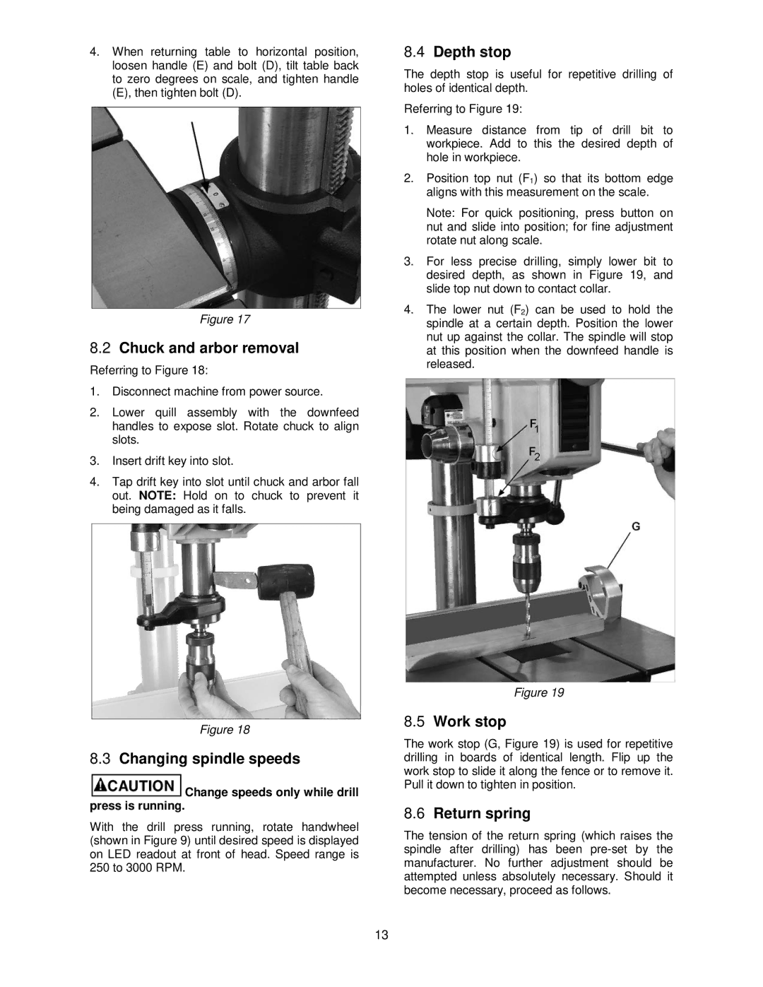
8.4Depth stop
The depth stop is useful for repetitive drilling of holes of identical depth.
Referring to Figure 19:
1.Measure distance from tip of drill bit to workpiece. Add to this the desired depth of hole in workpiece.
2.Position top nut (F1) so that its bottom edge aligns with this measurement on the scale.
Note: For quick positioning, press button on nut and slide into position; for fine adjustment rotate nut along scale.
3.For less precise drilling, simply lower bit to desired depth, as shown in Figure 19, and slide top nut down to contact collar.
4.The lower nut (F2) can be used to hold the spindle at a certain depth. Position the lower nut up against the collar. The spindle will stop at this position when the downfeed handle is released.
Figure 19
8.5Work stop
The work stop (G, Figure 19) is used for repetitive drilling in boards of identical length. Flip up the work stop to slide it along the fence or to remove it. Pull it down to tighten in position.
8.6Return spring
The tension of the return spring (which raises the spindle after drilling) has been
13