6.0Setup and assembly
6.1Shipping contents
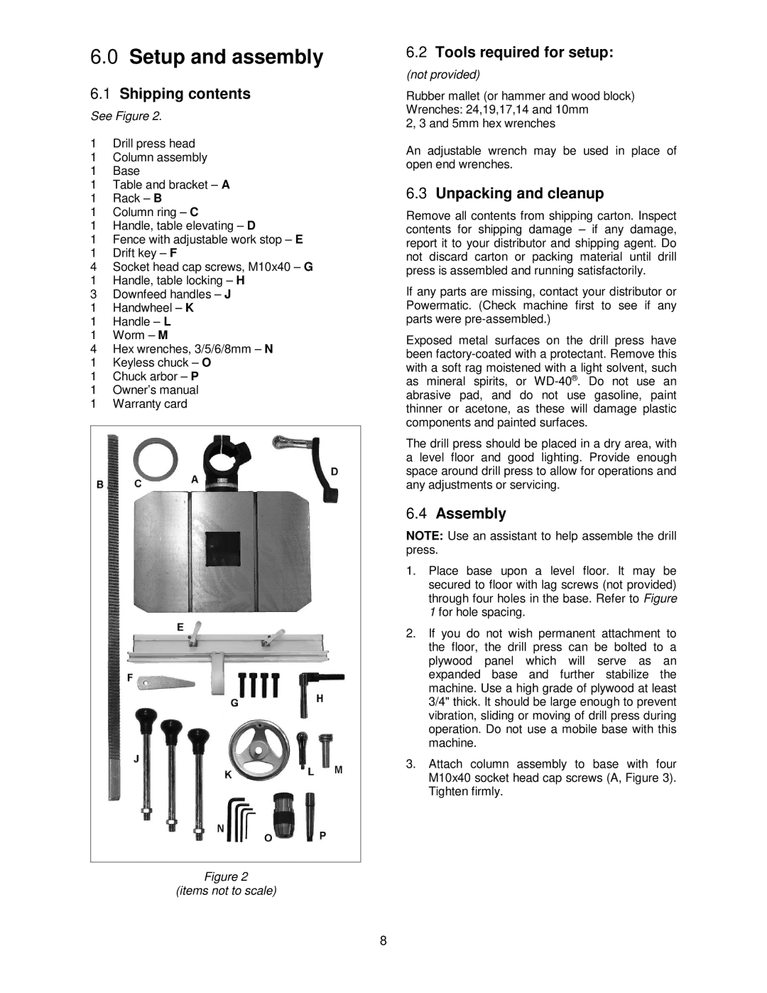
See Figure 2.
1Drill press head
1Column assembly
1Base
1Table and bracket – A
1Rack – B
1Column ring – C
1Handle, table elevating – D
1Fence with adjustable work stop – E
1Drift key – F
4Socket head cap screws, M10x40 – G
1Handle, table locking – H
3Downfeed handles – J
1Handwheel – K
1Handle – L
1Worm – M
4Hex wrenches, 3/5/6/8mm – N
1Keyless chuck – O
1Chuck arbor – P
1Owner’s manual
1Warranty card
Figure 2
(items not to scale)
6.2Tools required for setup:
(not provided)
Rubber mallet (or hammer and wood block) Wrenches: 24,19,17,14 and 10mm
2, 3 and 5mm hex wrenches
An adjustable wrench may be used in place of open end wrenches.
6.3Unpacking and cleanup
Remove all contents from shipping carton. Inspect contents for shipping damage – if any damage, report it to your distributor and shipping agent. Do not discard carton or packing material until drill press is assembled and running satisfactorily.
If any parts are missing, contact your distributor or Powermatic. (Check machine first to see if any parts were
Exposed metal surfaces on the drill press have been
The drill press should be placed in a dry area, with a level floor and good lighting. Provide enough space around drill press to allow for operations and any adjustments or servicing.
6.4Assembly
NOTE: Use an assistant to help assemble the drill press.
1.Place base upon a level floor. It may be secured to floor with lag screws (not provided) through four holes in the base. Refer to Figure 1 for hole spacing.
2.If you do not wish permanent attachment to the floor, the drill press can be bolted to a plywood panel which will serve as an expanded base and further stabilize the machine. Use a high grade of plywood at least 3/4" thick. It should be large enough to prevent vibration, sliding or moving of drill press during operation. Do not use a mobile base with this machine.
3.Attach column assembly to base with four M10x40 socket head cap screws (A, Figure 3). Tighten firmly.
8