Installing the Front Rail
1.Identify the front rail, which is 3" x 3" with notches on one side.
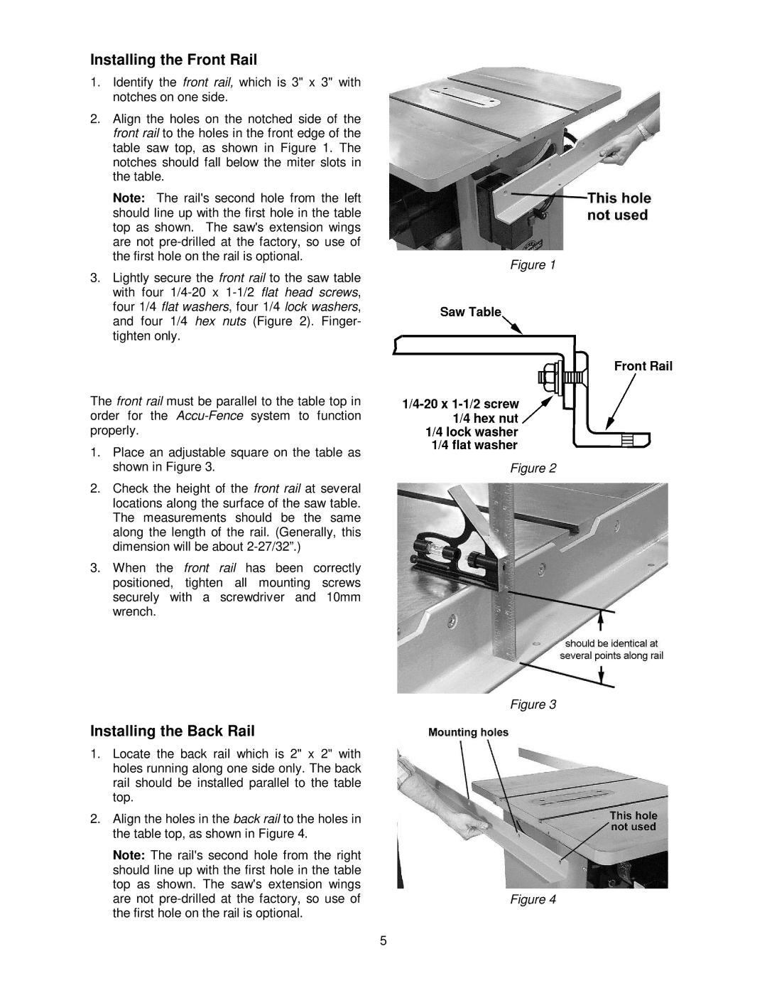
2.Align the holes on the notched side of the front rail to the holes in the front edge of the table saw top, as shown in Figure 1. The notches should fall below the miter slots in the table.
Note: The rail's second hole from the left should line up with the first hole in the table top as shown. The saw's extension wings are not
3.Lightly secure the front rail to the saw table with four
The front rail must be parallel to the table top in order for the
1.Place an adjustable square on the table as shown in Figure 3.
2.Check the height of the front rail at several locations along the surface of the saw table. The measurements should be the same along the length of the rail. (Generally, this dimension will be about
3.When the front rail has been correctly positioned, tighten all mounting screws securely with a screwdriver and 10mm wrench.
Installing the Back Rail
1.Locate the back rail which is 2" x 2" with holes running along one side only. The back rail should be installed parallel to the table top.
2.Align the holes in the back rail to the holes in the table top, as shown in Figure 4.
Note: The rail's second hole from the right should line up with the first hole in the table top as shown. The saw's extension wings are not
5
Figure 1
Figure 2
Figure 3
Figure 4