Installing the Table
The optional wood extension table (including the optional router table) sits flush against the saw table and along the inside of the rails. The Powermatic logo (or warning label on the router table) should face outward. The extension table is not bolted to the saw table. It is bolted only to the rails.
The extension table and saw table must be aligned properly so the
1.Place the extension table between the rails and up against the saw table, leaving the extension table raised just slightly above the saw table. Clamp the extension table to the front and back rails as shown in Figure 7. Clamping pressure should be enough to secure the table yet allow minor adjustments.
2.Use a rubber mallet (or a hammer and block of wood) to tap the extension table up flush against the cast iron saw table (Figure 6). Then tap down the extension table at various points along its edge where it meets the saw table, until it is level with the saw table (Figure 8).
3.As one part of the edge becomes level with the table, tighten the clamp on that side. Then move to the other side and repeat, until the full length of the edge is level with the saw table.
4.Lay a straight edge across both extension table and saw table to ensure proper leveling.
5.When extension table is properly aligned, drill holes into the wood table using the holes in the rails as your guide. See Figure 9. (You may wish to drill 3/32" pilot holes first.) Drill 1/4" holes into the front edge of the table using the holes in the front rail as a guide. Drill 5/16" holes into the back edge of the table using the holes in the back rail as a guide.
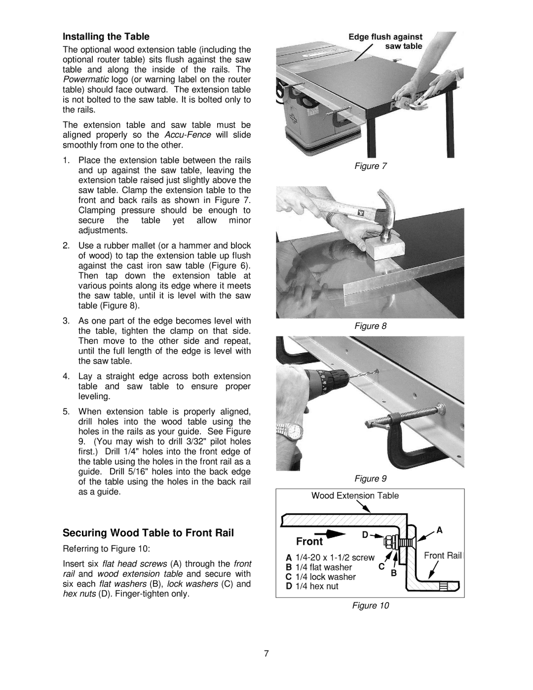
Securing Wood Table to Front Rail
Referring to Figure 10:
Insert six flat head screws (A) through the front rail and wood extension table and secure with six each flat washers (B), lock washers (C) and hex nuts (D).
Figure 7
Figure 8
Figure 9
Figure 10
7