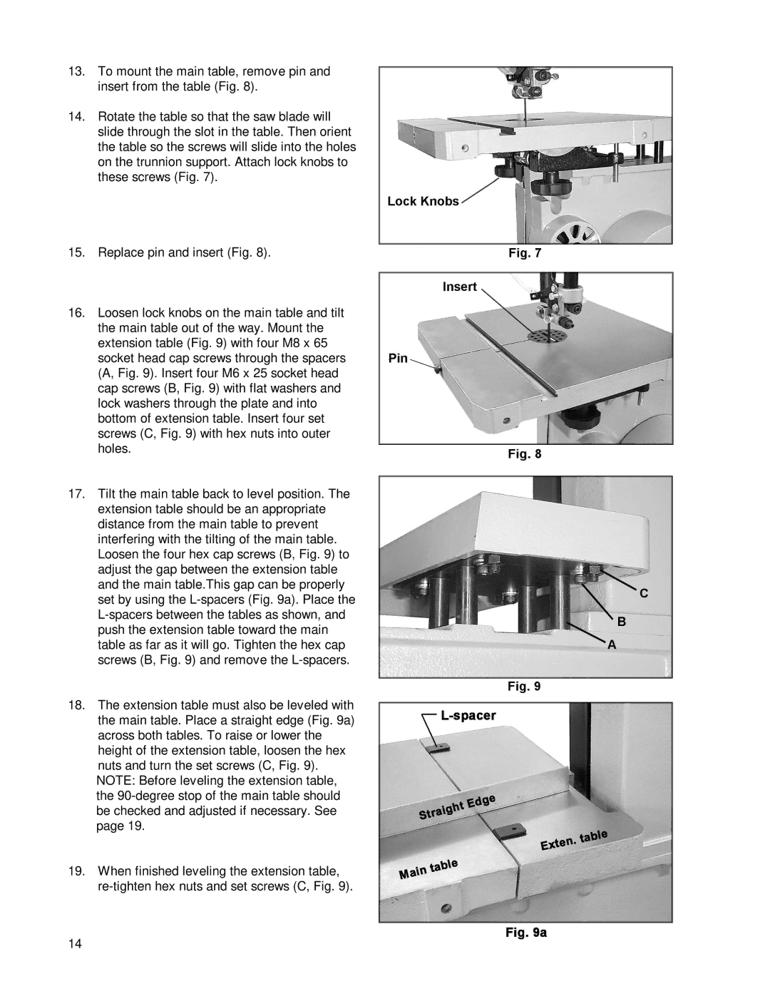
13.To mount the main table, remove pin and insert from the table (Fig. 8).
14.Rotate the table so that the saw blade will slide through the slot in the table. Then orient the table so the screws will slide into the holes on the trunnion support. Attach lock knobs to these screws (Fig. 7).
15.Replace pin and insert (Fig. 8).
16.Loosen lock knobs on the main table and tilt the main table out of the way. Mount the extension table (Fig. 9) with four M8 x 65 socket head cap screws through the spacers (A, Fig. 9). Insert four M6 x 25 socket head cap screws (B, Fig. 9) with flat washers and lock washers through the plate and into bottom of extension table. Insert four set screws (C, Fig. 9) with hex nuts into outer holes.
17.Tilt the main table back to level position. The extension table should be an appropriate distance from the main table to prevent interfering with the tilting of the main table. Loosen the four hex cap screws (B, Fig. 9) to adjust the gap between the extension table and the main table.This gap can be properly set by using the
18.The extension table must also be leveled with the main table. Place a straight edge (Fig. 9a) across both tables. To raise or lower the height of the extension table, loosen the hex nuts and turn the set screws (C, Fig. 9). NOTE: Before leveling the extension table, the
19.When finished leveling the extension table,
14