Adjusting Lower Blade Guide and Blade Support Bearing
1.Disconnect machine from power source.
2.Blade must already be tensioned and tracking properly.
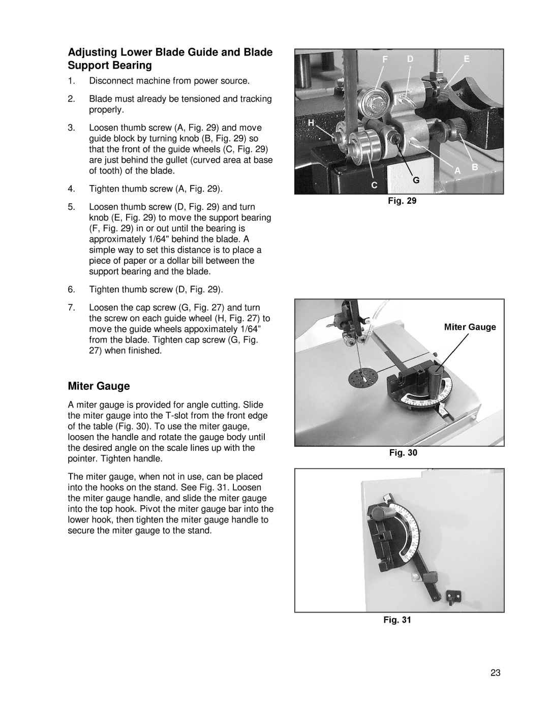
3.Loosen thumb screw (A, Fig. 29) and move guide block by turning knob (B, Fig. 29) so that the front of the guide wheels (C, Fig. 29) are just behind the gullet (curved area at base of tooth) of the blade.
4.Tighten thumb screw (A, Fig. 29).
5.Loosen thumb screw (D, Fig. 29) and turn knob (E, Fig. 29) to move the support bearing (F, Fig. 29) in or out until the bearing is approximately 1/64" behind the blade. A simple way to set this distance is to place a piece of paper or a dollar bill between the support bearing and the blade.
6.Tighten thumb screw (D, Fig. 29).
7.Loosen the cap screw (G, Fig. 27) and turn the screw on each guide wheel (H, Fig. 27) to move the guide wheels appoximately 1/64” from the blade. Tighten cap screw (G, Fig. 27) when finished.
Miter Gauge
A miter gauge is provided for angle cutting. Slide the miter gauge into the
The miter gauge, when not in use, can be placed into the hooks on the stand. See Fig. 31. Loosen the miter gauge handle, and slide the miter gauge into the top hook. Pivot the miter gauge bar into the lower hook, then tighten the miter gauge handle to secure the miter gauge to the stand.
23