8.Set the top panel in place on the columns and secure with M4 × 10 screws provided. Do not tighten at this time. (See FIG.8)
Figure 8-Top panel installation
9.Attach the screens to columns with M4 × 10 screws provided. Do not tighten at this time. (See FIG.9)
Figure 9-Screens installation
10.Tighten the screws of step 8,9,10 to finish installation.
11.Attach the handle to the middle base with 2 hex head screws provided. (See FIG.10)
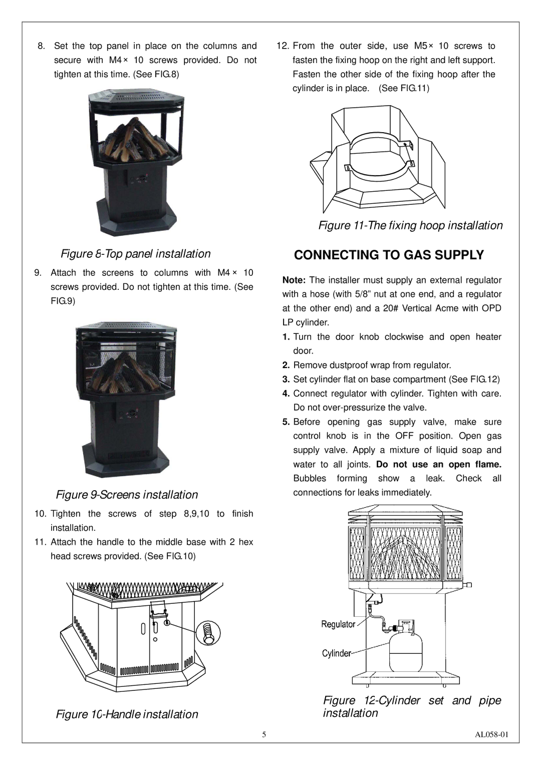
12.From the outer side, use M5× 10 screws to fasten the fixing hoop on the right and left support. Fasten the other side of the fixing hoop after the cylinder is in place. (See FIG.11)
Figure 11-The fixing hoop installation
CONNECTING TO GAS SUPPLY
Note: The installer must supply an external regulator with a hose (with 5/8” nut at one end, and a regulator at the other end) and a 20# Vertical Acme with OPD LP cylinder.
1.Turn the door knob clockwise and open heater door.
2.Remove dustproof wrap from regulator.
3.Set cylinder flat on base compartment (See FIG.12)
4.Connect regulator with cylinder. Tighten with care. Do not
5.Before opening gas supply valve, make sure control knob is in the OFF position. Open gas supply valve. Apply a mixture of liquid soap and water to all joints. Do not use an open flame. Bubbles forming show a leak. Check all connections for leaks immediately.
Figure | Figure |
installation |
5 |