WARNING:Make sure that power

is turn off before proceeding....

OBSERVED PROBLEM

No spark when press in ignition button

When

pressing the button of ignitor

button

is pressed, there is spark at

ODS/pilot but no ignition

ODS/pilot lights but flame is continuous igniting and the main burner couldn’t be lit.

TROUBLESHOOTING

WARNING: Turn off and let cool before servicing. Only a qualified service person should service and repair fireplace.

POSSIBLECAUSE

1.No power to heater

2.No battery in transmitter or battery isn’t correctly assembly

1.Gas supply turned off or equip- ment shut off valve closed

2.Air in gas lines when installed.

3.Depleted gas supply

4.ODS/pilot is clogged

5.Gas regulator setting is not correct

6.Pilot electrude position is not correct

7.Wire is not correct or loosen

8 Gas valve is damage

1.Thermocouple connection loose at control board

2.Pilot flame not touching thermcouple which allows thermo- couple to cool, causing pilot flame to go out. This problem could be caused by one or both of the following

A)Low gas pressure

B)Dirty or partially clogged ODS/ pilot

3.Thermocouple damaged

4.Control valve damaged

CAUTION: Never use a wire, needle, or similar object to clean ODS/pilot. This can damage ODS/ pilot unit.

REMEDY

1.Check the electric power

2.Place or replace the battery.

1.Turn on gas supply or open equipment shutoff valve

2

Press ON/OFF button again


until air

is removed .

.


3.

Contact

local propane/LP

gas

company

4Clean ODS/pilot (see Cleaning and

Maintenance,page 13 ) or replace ODS/pilot assembly

5.Replace gas control

6.Replace Pilot

7.Check the wine and make wine correct.

8.Replace gas valve

1.Hand tighten until snug, then tighten 1/4 turn more.

2.A) Contact local propane/LP gas company.

B)Clean ODS/pilot (see Cleaning and Maintenance, page 13) or

replace

ODS/pilot assembly

3.Replace thermocouple

4.Replace control valve

Burner does not light after ODS/pilot

1.

Burner orifice clogged

1.Clean burner (see Cleaning

is lit

2.

Inlet gas pressure is too low


and

Maintenance, page 13) or


3.

Burner orifice diameter is too

replace

burner orifice.


small

2.

Contact

local

propane/LP


4.

Thermocouple leads discon-

gas company


nected or improperly connected

3.

Replace

burner

orifice


5.

Burners will not come in

4.

Reconnect leads (see wiring

remote position

diagram)


5. Replace battery in transmitter


and receiver

1 6

Page 16
Image 16
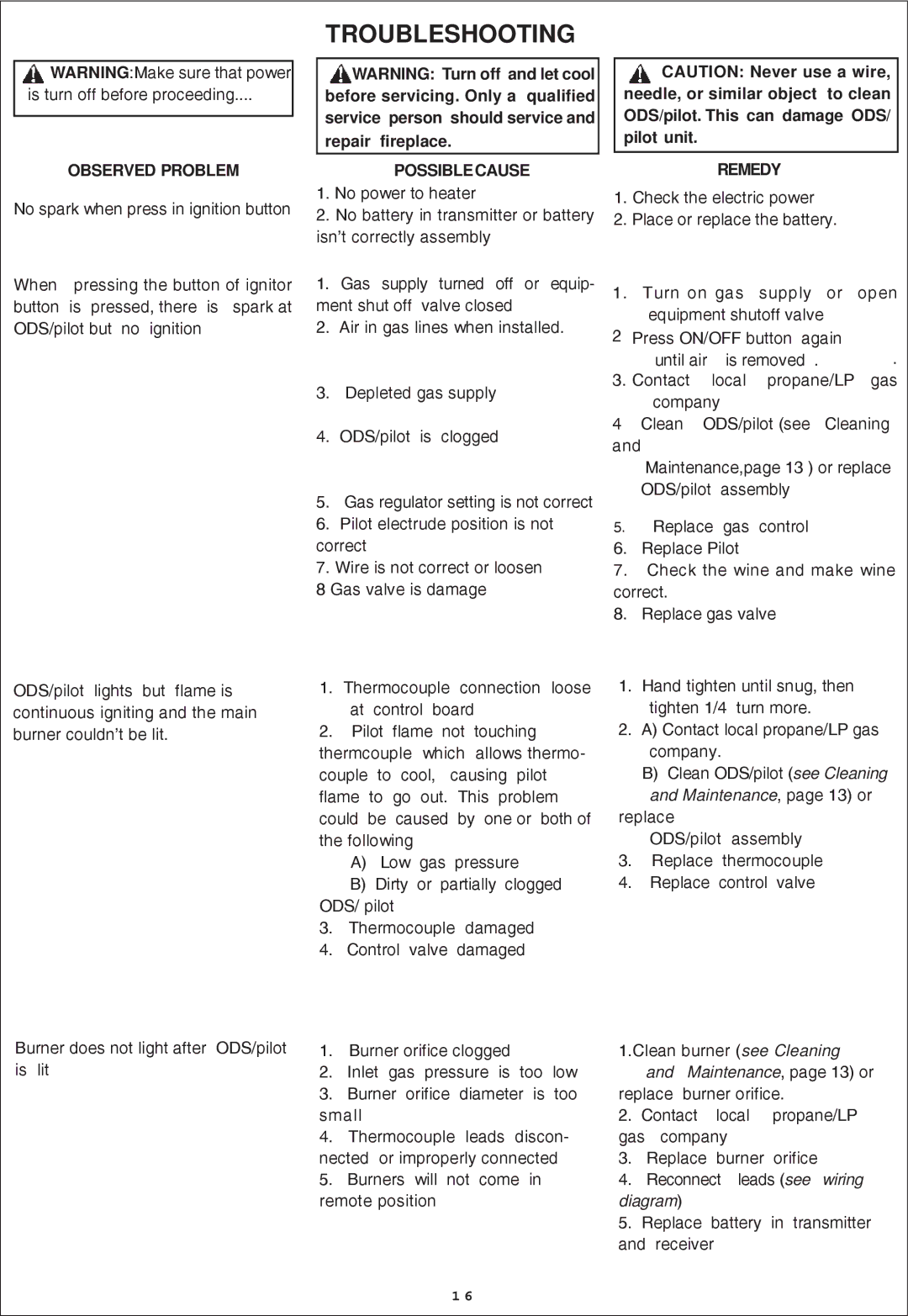
Procom QN300RYLA-W, QL300RYLA-W installation manual Observed Problem, Possiblecause, Remedy

QN300RYLA-W, QN300RYLA, QL300RYLA, QL300RYLA-W specifications

The Procom QN300RYLA-W, QN300RYLA, QL300RYLA-W, and QL300RYLA are advanced antenna solutions designed for diverse communication needs. These models exemplify cutting-edge technology and innovative design, catering to clients in various sectors, from telecommunications to public safety.

One of the standout features of the Procom antennas is their robust frequency range. The QN300RYLA-W and QN300RYLA models typically support a frequency range of 300 to 470 MHz, while the QL300RYLA-W and QL300RYLA operate in the same bandwidth, providing flexibility for various applications. This capability ensures compatibility with a broad array of devices, enhancing communication reliability.

Procom’s design philosophy emphasizes durability and performance. The antennas are constructed with high-quality materials that can withstand a wide range of environmental conditions. With their weather-resistant properties, these antennas can be deployed in challenging regions, ensuring continuous operation in rain or shine.

The gain characteristics of the antennas are optimized for long-range communication. With gains typically reaching up to 6 dBi, they provide enhanced signal strength and coverage, crucial for critical communications. This is particularly beneficial in urban environments where signal degradation often occurs due to physical obstructions.

Another significant aspect of the Procom QN and QL series is their installation versatility. They can be mounted in different configurations, including vertical or horizontal setup, adapting to specific user requirements and site conditions. This flexibility allows for streamlined deployment in various settings, including rooftops, towers, and vehicles.

These antennas also integrate advanced radiation patterns, which help minimize interference and improve overall performance. This ensures reliable transmission over considerable distances, making them ideal for applications in emergency services, transportation logistics, and industrial communications.

In summary, the Procom QN300RYLA-W, QN300RYLA, QL300RYLA-W, and QL300RYLA antennas deliver exceptional performance, robust design, and versatility for a myriad of communication scenarios. With their advanced technology and user-centric features, these antennas are well-suited to meet the evolving demands of modern communication needs.