3. Add the Btu/Hr of all fuel burning appliances in the space.


Vent-free heater


Btu/Hr

Example:


Gas water heater*


Btu/Hr


Gas water heater


30,000

Btu/Hr

Gas furnace


Btu/Hr


Vented gas heater


Btu/Hr

Vent-free heater

+

26,000

Btu/Hr


Gas heater logs


Btu/Hr

Total

=

56,000

Btu/Hr

Other gas appliances* +


Btu/Hr


Total

=


Btu/Hr


*Do not include direct-vent gas appliances. Direct-vent draws combustion air from the outdoors and vents to the outdoors.

4. Compare the maximum Btu/Hr the space can support with the actual amount of Btu/Hr used. Btu/Hr (maximum the space can support)

Btu/Hr (actual amount of Btu/Hr used)

Example : 51,200 Btu/Hr(maximum the space can support) 56,000 Btu/Hr(actual amount of Btu/Hr used)

The space in the above example is a confined space because the actual Btu/Hr used is more than the maximum Btu/Hr the space can support.

You must provide additional fresh air. Your options are as follows:

A. Rework worksheet, adding the space of an adjoining room. If the extra space provides an unconfined space, remove door to adjoining room or add ventilation grills between rooms. See Ventilation Air From Inside Building.

B. Vent room directly to the outdoors. See Ventilation Air From Outdoors .

C. Install a lower Btu/Hr heater, if lower Btu/Hr size makes room unconfined.

If the actual Btu/Hr used is less than the maximum Btu/Hr the space can support, the space is an unconfined space. You will need no additional fresh air ventilation.

WARNING: If the area in which the heater may be operated is smaller than that defined as an unconfined space or if the building is of unusually tight construction, provide adequate combustion and ventilation air by one of the methods described in the National Fuel Gas Code, ANS Z223.1, Section 5.3 or applicable local codes.

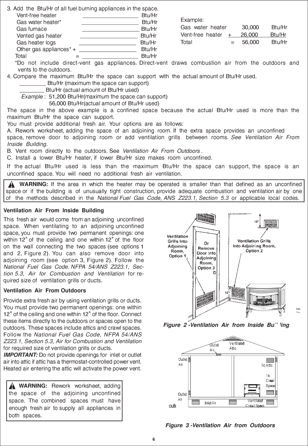
Ventilation Air From lnside Building

This fresh air would come from an adjoining unconfined space. When ventilating to an adjoining unconfined space, you must provide two permanent openings: one within 12" of the ceiling and one within 12" of the floor on the wall connecting the two spaces (see options 1 and 2, Figure 2). You can also remove door into adjoining room (see option 3, Figure 2). Follow the National Fuel Gas Code. NFPA 54/ANS Z223.1, Sec- tion 5.3, Air for Combustion and Ventilation for re- quired size of ventilation grills or ducts.

Ventilation Air From Outdoors

Provide extra fresh air by using ventilation grills or ducts. You must provide two permanent openings: one within 12" of the ceiling and one within 12" of the floor. Connect these items directly to the outdoors or spaces open to the outdoors. These spaces include attics and crawl spaces. Follow the National Fuel Gas Code, NFPA 54/ANS Z223.1, Section 5.3, Air for Combustion and Ventilation for required size of ventilation grills or ducts.

IMPORTANT: Do not provide openings for inlet or outlet air into attic if attic has a thermostat-controlled power vent. Heated air entering the attic will activate the power vent.

WARNING: Rework worksheet, adding the space of the adjoining unconfined space. The combined spaces must have enough fresh air to supply all appliances in both spaces.

Figure 2 -Ventilation Air from Inside Building

outlet

Figure 3 -Ventilation Air from Outdoors

6

Page 6
Image 6
Procom QN300RYLA-W, QL300RYLA-W Ventilation Air From lnside Building, Ventilation Air From Outdoors

QN300RYLA-W, QN300RYLA, QL300RYLA, QL300RYLA-W specifications

The Procom QN300RYLA-W, QN300RYLA, QL300RYLA-W, and QL300RYLA are advanced antenna solutions designed for diverse communication needs. These models exemplify cutting-edge technology and innovative design, catering to clients in various sectors, from telecommunications to public safety.

One of the standout features of the Procom antennas is their robust frequency range. The QN300RYLA-W and QN300RYLA models typically support a frequency range of 300 to 470 MHz, while the QL300RYLA-W and QL300RYLA operate in the same bandwidth, providing flexibility for various applications. This capability ensures compatibility with a broad array of devices, enhancing communication reliability.

Procom’s design philosophy emphasizes durability and performance. The antennas are constructed with high-quality materials that can withstand a wide range of environmental conditions. With their weather-resistant properties, these antennas can be deployed in challenging regions, ensuring continuous operation in rain or shine.

The gain characteristics of the antennas are optimized for long-range communication. With gains typically reaching up to 6 dBi, they provide enhanced signal strength and coverage, crucial for critical communications. This is particularly beneficial in urban environments where signal degradation often occurs due to physical obstructions.

Another significant aspect of the Procom QN and QL series is their installation versatility. They can be mounted in different configurations, including vertical or horizontal setup, adapting to specific user requirements and site conditions. This flexibility allows for streamlined deployment in various settings, including rooftops, towers, and vehicles.

These antennas also integrate advanced radiation patterns, which help minimize interference and improve overall performance. This ensures reliable transmission over considerable distances, making them ideal for applications in emergency services, transportation logistics, and industrial communications.

In summary, the Procom QN300RYLA-W, QN300RYLA, QL300RYLA-W, and QL300RYLA antennas deliver exceptional performance, robust design, and versatility for a myriad of communication scenarios. With their advanced technology and user-centric features, these antennas are well-suited to meet the evolving demands of modern communication needs.