WARNING: Never connect heater to private (non-utility) gas wells. This gas is commonly known as wellhead gas.

CAUTION: Use only new, black iron or steel pipe. Internally-tinned copper tubing may be used in certain areas. Check your local

codes. Use pipe of 1/2" diameter or greater to allow proper volume gas to heater. If pipe is too small, undue loss of pressure will occur.

Installation must include an equip- ment shutoff valve, union, and plugged 1/8" NPT tap. Locate NPT tap within reach for test gauge hook up. NPT tap must be upstream from heater (see Figure 7).

IMPORTANT: Install equipment shutoff valve in an accessible location. The equipment shutoff valve is for turning on or shutting off the gas to the appliance. Apply pipe joint sealant lightly to male

CAUTION: Avoid damage to regulator. Hold gas regulator with wrench when connecting into gas piping and/or fittings.

CHECKING GAS

CONNECTIONS

WARNING: Test all gas piping and connections for leaks after installing or servicing. Correct all leaks at once.

WARNING: Never use an open flame to check for a leak. Apply a mixture of liquid soap and water to all joints. Bubbles forming show a leak. Correct all leaks at once.

CAUTION: Make sure external regulator has been installed be- tween gas supply and heater. See guidelines under Connecting to Gas Supply.

Pressure Testing Gas Supply Piping System

Test Pressures In Excess Of 1/2 PSIG(3.5kPa)

1.Disconnect heater with its appliance main gas valve (control valve) and equipment shutoff valve from gas supply piping system. Pressures in excess of 1/2 PSIG will damage heater regulator.

2.Cap off open end of gas pipe where equipment shutoff valve was connected.

3.Pressurize supply piping system by either using compressed air or opening gas supply tank valve.

4.Check all joints of gas supply piping system. Apply mixture of liquid soap and water to gas joints. Bubbles forming show a leak.

5.Correct all leaks at once.

6.Reconnect heater and equipment shutoff valve to gas supply. Check reconnected fittings for leaks.

threads.This will prevent excess sealant from going into pipe. Excess sealant in pipe could result in clogged heater valves.

CAUTION: Use pipe joint sealant that is resistant to gas (PROPANE or NG).

We recommend that you install a sediment trap in supply line as shown in Figure 7. Locate sediment trap where it is within reach for cleaning. Install in piping system between fuel supply and heater. Locate sediment trap where trapped matter is not likely to freeze. A sediment trap traps moisture and contaminants. This keeps them from going into heater controls. If sediment trap is not installed or is installed incorrectly, heater may not run properly.

Pressure Testing Heater

Gas Connections

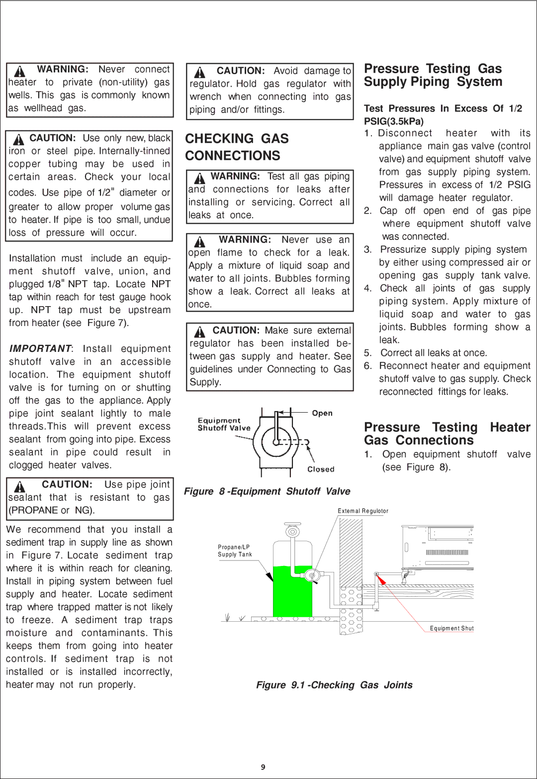
1. Open equipment shutoff valve (see Figure 8).

Figure 8 -Equipment Shutoff Valve

E xte m a l R e guloto r

P rop an e/LP

S u pp ly T a nk

E q uipm en t S h ut

Figure 9.1 -Checking Gas Joints

9

Page 9
Image 9
Procom QN300RYLA-W, QL300RYLA-W installation manual Checking GAS Connections, Test Pressures In Excess Of 1/2 PSIG3.5kPa

QN300RYLA-W, QN300RYLA, QL300RYLA, QL300RYLA-W specifications

The Procom QN300RYLA-W, QN300RYLA, QL300RYLA-W, and QL300RYLA are advanced antenna solutions designed for diverse communication needs. These models exemplify cutting-edge technology and innovative design, catering to clients in various sectors, from telecommunications to public safety.

One of the standout features of the Procom antennas is their robust frequency range. The QN300RYLA-W and QN300RYLA models typically support a frequency range of 300 to 470 MHz, while the QL300RYLA-W and QL300RYLA operate in the same bandwidth, providing flexibility for various applications. This capability ensures compatibility with a broad array of devices, enhancing communication reliability.

Procom’s design philosophy emphasizes durability and performance. The antennas are constructed with high-quality materials that can withstand a wide range of environmental conditions. With their weather-resistant properties, these antennas can be deployed in challenging regions, ensuring continuous operation in rain or shine.

The gain characteristics of the antennas are optimized for long-range communication. With gains typically reaching up to 6 dBi, they provide enhanced signal strength and coverage, crucial for critical communications. This is particularly beneficial in urban environments where signal degradation often occurs due to physical obstructions.

Another significant aspect of the Procom QN and QL series is their installation versatility. They can be mounted in different configurations, including vertical or horizontal setup, adapting to specific user requirements and site conditions. This flexibility allows for streamlined deployment in various settings, including rooftops, towers, and vehicles.

These antennas also integrate advanced radiation patterns, which help minimize interference and improve overall performance. This ensures reliable transmission over considerable distances, making them ideal for applications in emergency services, transportation logistics, and industrial communications.

In summary, the Procom QN300RYLA-W, QN300RYLA, QL300RYLA-W, and QL300RYLA antennas deliver exceptional performance, robust design, and versatility for a myriad of communication scenarios. With their advanced technology and user-centric features, these antennas are well-suited to meet the evolving demands of modern communication needs.