CLEARANCESTOCOMBUSTIBLES (Vent-Free Operation Only) Carefully follow the instructions below. This stove is a freestanding unit designed to set directly on the floor.

IMPORTANT: You must maintain minimum wall and ceiling clearances during installation. The minimum clearances are shown in Figure 4. Measure from outermost point of stove top.

Minimum Wall and Ceiling Clearances

(see Figure 4)

A. Clearances from outermost point of stove top to any combustible side wall should not be less than 24 inches.

B.Clearances from outermost point of stove top to any combustible back wall should not be less than 10

i n c h e s ( l n c l u d e s

c o r n e r

installations).


C.Clearances from the stove top to the ceiling should not be less than 48 inches.

CONNECTING TO GAS SUPPLY

WARNING: A qualified ser- vice person must connect heater to gas supply. Follow all local codes.

CAUTION: Never

connect

heater directly to the gas supply.

This heater

requires an

external

regulator (not

supplied). lnstall the

external regulator between the heater

and gas supply.


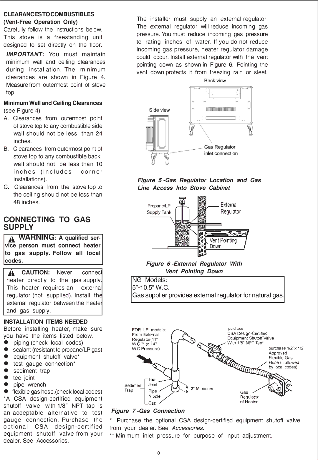
INSTALLATION ITEMS NEEDED Before installing heater, make sure you have the items listed below.

piping (check local codes) sealant (resistant to propane/LP gas) equipment shutoff valve*

test gauge connection* sediment trap

tee joint pipe wrench

flexible gas hose.(check local codes) *A CSA design-certified equipment shutoff valve with 1/8" NPT tap is an acceptable alternative to test gauge connection. Purchase the optional CSA design-certified equipment shutoff valve from your dealer. See Accessories.

The installer must supply an external regulator. The external regulator will reduce incoming gas pressure. You must reduce incoming gas pressure to rating inches of water. If you do not reduce incoming gas pressure, heater regulator damage could occur. lnstall external regulator with the vent pointing down as shown in Figure 6. Pointing the vent down protects it from freezing rain or sleet.

Figure 5 -Gas Regulator Location and Gas

Line Access Into Stove Cabinet

Propane/LP

Supply Tank

Figure 6 -External Regulator With

Vent Pointing Down

NG Models:

5”-10.5” W.C.

Gas supplier provides external regulator for natural gas.

purchase

Figure 7 -Gas Connection

*Purchase the optional CSA design-certified equipment shutoff valve from your dealer. See Accessories.

**Minimum inlet pressure for purpose of input adjustment.

8

Page 8
Image 8
Procom QN300RYLA-W, QL300RYLA-W installation manual Connecting to GAS Supply, Minimum Wall and Ceiling Clearances

QN300RYLA-W, QN300RYLA, QL300RYLA, QL300RYLA-W specifications

The Procom QN300RYLA-W, QN300RYLA, QL300RYLA-W, and QL300RYLA are advanced antenna solutions designed for diverse communication needs. These models exemplify cutting-edge technology and innovative design, catering to clients in various sectors, from telecommunications to public safety.

One of the standout features of the Procom antennas is their robust frequency range. The QN300RYLA-W and QN300RYLA models typically support a frequency range of 300 to 470 MHz, while the QL300RYLA-W and QL300RYLA operate in the same bandwidth, providing flexibility for various applications. This capability ensures compatibility with a broad array of devices, enhancing communication reliability.

Procom’s design philosophy emphasizes durability and performance. The antennas are constructed with high-quality materials that can withstand a wide range of environmental conditions. With their weather-resistant properties, these antennas can be deployed in challenging regions, ensuring continuous operation in rain or shine.

The gain characteristics of the antennas are optimized for long-range communication. With gains typically reaching up to 6 dBi, they provide enhanced signal strength and coverage, crucial for critical communications. This is particularly beneficial in urban environments where signal degradation often occurs due to physical obstructions.

Another significant aspect of the Procom QN and QL series is their installation versatility. They can be mounted in different configurations, including vertical or horizontal setup, adapting to specific user requirements and site conditions. This flexibility allows for streamlined deployment in various settings, including rooftops, towers, and vehicles.

These antennas also integrate advanced radiation patterns, which help minimize interference and improve overall performance. This ensures reliable transmission over considerable distances, making them ideal for applications in emergency services, transportation logistics, and industrial communications.

In summary, the Procom QN300RYLA-W, QN300RYLA, QL300RYLA-W, and QL300RYLA antennas deliver exceptional performance, robust design, and versatility for a myriad of communication scenarios. With their advanced technology and user-centric features, these antennas are well-suited to meet the evolving demands of modern communication needs.